Infiniti QX56 (JA60). Manual — part 381
EC-176
< COMPONENT DIAGNOSIS >
[VK56DE]
P0171, P0174 FUEL INJECTION SYSTEM FUNCTION
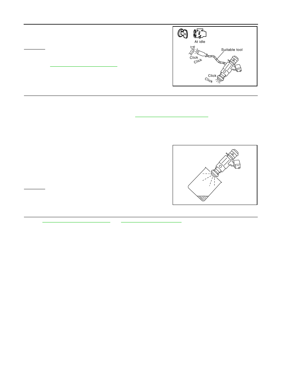
2. Listen to each fuel injector operating sound.
OK or NG
OK
>> GO TO 8.
NG
>> Perform trouble diagnosis for FUEL INJECTOR, refer to
.
8.
CHECK FUEL INJECTOR
1. Confirm that the engine is cooled down and there are no fire hazards near the vehicle.
2. Turn ignition switch OFF.
3. Disconnect all fuel injector harness connectors.
4. Remove fuel injector gallery assembly. Refer to
EM-40, "Removal and Installation"
Keep fuel hose and all fuel injectors connected to fuel injector gallery.
5. For DTC P0171, reconnect fuel injector harness connectors on bank 1.
For DTC P0174, reconnect fuel injector harness connectors on bank 2.
6. Disconnect all ignition coil harness connectors.
7. Prepare pans or saucers under each fuel injector.
8. Crank engine for about 3 seconds.
For DTC P0171, make sure that fuel sprays out from fuel injec-
tors on bank 1.
For DTC P0174, make sure that fuel sprays out from fuel injec-
tors on bank 2.
OK or NG
OK
>> GO TO 9.
NG
>> Replace fuel injectors from which fuel does not spray
out. Always replace O-ring with new ones.
9.
CHECK INTERMITTENT INCIDENT
GI-35, "How to Check Terminal"
and
GI-38, "Intermittent Incident"
>> INSPECTION END
Clicking noise should be heard.
PBIB1986E
Fuel should be sprayed evenly for each fuel injector.
PBIB1726E
P0172, P0175 FUEL INJECTION SYSTEM FUNCTION
EC-177
< COMPONENT DIAGNOSIS >
[VK56DE]
C
D
E
F
G
H
I
J
K
L
M
A
EC
N
P
O
P0172, P0175 FUEL INJECTION SYSTEM FUNCTION
On Board Diagnosis Logic
INFOID:0000000005149193
With the Air/Fuel Mixture Ratio Self-Learning Control, the actual mixture ratio can be brought closely to the
theoretical mixture ratio based on the mixture ratio feedback signal from the A/F sensors 1. The ECM calcu-
lates the necessary compensation to correct the offset between the actual and the theoretical ratios.
In case the amount of the compensation value is extremely large (The actual mixture ratio is too rich.), the
ECM judges the condition as the fuel injection system malfunction and lights up the MIL (2 trip detection logic).
DTC Confirmation Procedure
INFOID:0000000005167701
NOTE:
If DTC Confirmation Procedure has been previously conducted, always perform the following procedure
before conducting the next step.
1. Turn ignition switch OFF and wait at least 10 seconds.
2. Turn ignition switch ON.
3. Turn ignition switch OFF and wait at least 10 seconds.
WITH CONSULT-III
1. Start engine and warm it up to normal operating temperature.
2. Turn ignition switch OFF and wait at least 10 seconds.
3. Turn ignition switch ON.
4. Turn ignition switch OFF and wait at least 10 seconds.
5. Turn ignition switch ON and select “SELF-LEARNING CONT” in “WORK SUPPORT” mode with CON-
SULT-III.
6. Clear the self-learning control coefficient by touching “CLEAR”.
7. Start engine.
If it is difficult to start engine, the fuel injection system has a malfunction.
Performing the following procedure is advised.
a. Crank engine while depressing accelerator pedal.
NOTE:
When depressing accelerator pedal three-fourths (3/4) or more, the control system does not start the
engine. Do not depress accelerator pedal too much.
b. If engine starts, go to
.
If engine does not start, check exhaust and intake air leakage visually.
8. Keep engine at idle for least 5 minutes.
9. Check 1st trip DTC.
10. The 1st trip DTC P0172 or P0175 should be detected at this stage, if a malfunction exists. If so, go to
NOTE:
If 1st trip DTC is not detected during above procedure, performing the following procedure is advised.
a. Turn ignition switch OFF and wait at least 10 seconds.
b. Start engine.
Sensor
Input signal to ECM
ECM function
Actuator
A/F sensor 1
Density of oxygen in exhaust gas
(Mixture ratio feedback signal)
Fuel injection control
Fuel injector
DTC No.
Trouble diagnosis name
DTC detecting condition
Possible cause
P0172
0172
(Bank 1)
Fuel injection system too
rich
• Fuel injection system does not operate properly.
• The amount of mixture ratio compensation is too
large. (The mixture ratio is too rich.)
• A/F sensor 1
• Fuel injector
• Exhaust gas leaks
• Incorrect fuel pressure
• Mass air flow sensor
P0175
0175
(Bank 2)
EC-178
< COMPONENT DIAGNOSIS >
[VK56DE]
P0172, P0175 FUEL INJECTION SYSTEM FUNCTION
c.
Maintain the following conditions for at least 10 consecutive minutes.
Hold the accelerator pedal as steady as possible.
CAUTION:
Always drive vehicle at a safe speed.
d. Check 1st trip DTC.
e. If 1st trip DTC is detected, go to
WITH GST
1. Start engine and warm it up to normal operating temperature.
2. Turn ignition switch OFF and wait at least 10 seconds.
3. Turn ignition switch ON.
4. Turn ignition switch OFF and wait at least 10 seconds.
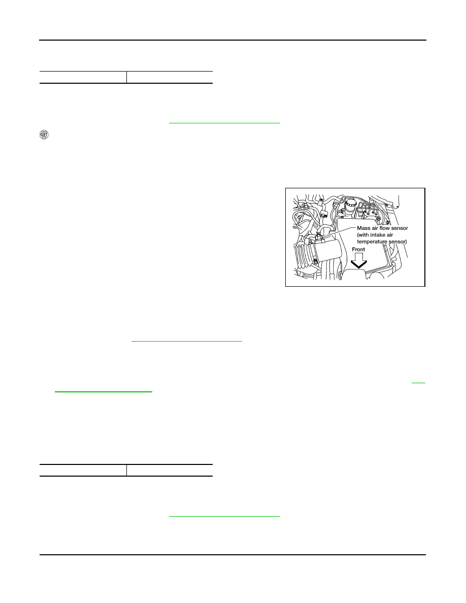
5. Disconnect mass air flow sensor harness connector.
6. Restart engine and let it idle for at least 5 seconds.
7. Stop engine and reconnect mass air flow sensor harness con-
nector.
8. Select Service $03 with GST. Make sure DTC P0102 is
detected.
9. Select Service $04 with GST and erase the DTC P0102.
10. Start engine.
If it is difficult to start engine, the fuel injection system has a mal-
function.
Performing the following procedure is advised.
a. Crank engine while depressing accelerator pedal.
NOTE:
When depressing accelerator pedal three-fourths (3/4) or more, the control system does not start the
engine. Do not depress accelerator pedal too much.
b. If engine starts, go to
.
If engine does not start, check exhaust and intake air leakage visually.
11. Keep engine at idle for at least 5 minutes.
12. Check 1st trip DTC.
13. The 1st trip DTC P0172 or P0175 should be detected at this stage, if a malfunction exists. If so, go to
NOTE:
If 1st trip DTC is not detected during above procedure, performing the following procedure is advised.
a. Turn ignition switch OFF and wait at least 10 seconds.
b. Start engine.
c.
Maintain the following conditions for at least 10 consecutive minutes.
Hold the accelerator pedal as steady as possible.
CAUTION:
Always drive vehicle at a safe speed.
d. Check 1st trip DTC.
e. If 1st trip DTC is detected, go to
Diagnosis Procedure
INFOID:0000000005149195
1.
CHECK EXHAUST GAS LEAK
1. Start engine and run it at idle.
VHCL SPEED SE
50 - 120 km/h (31 - 75 MPH)
VHCL SPEED SE
50 - 120 km/h (31 - 75 MPH)
BBIA0368E
P0172, P0175 FUEL INJECTION SYSTEM FUNCTION
EC-179
< COMPONENT DIAGNOSIS >
[VK56DE]
C
D
E
F
G
H
I
J
K
L
M
A
EC
N
P
O
2. Listen for an exhaust gas leak before three way catalyst (manifold).
OK or NG
OK
>> GO TO 2.
NG
>> Repair or replace.
2.
CHECK FOR INTAKE AIR LEAK
Listen for an intake air leak after the mass air flow sensor.
OK or NG
OK
>> GO TO 3.
NG
>> Repair or replace.
3.
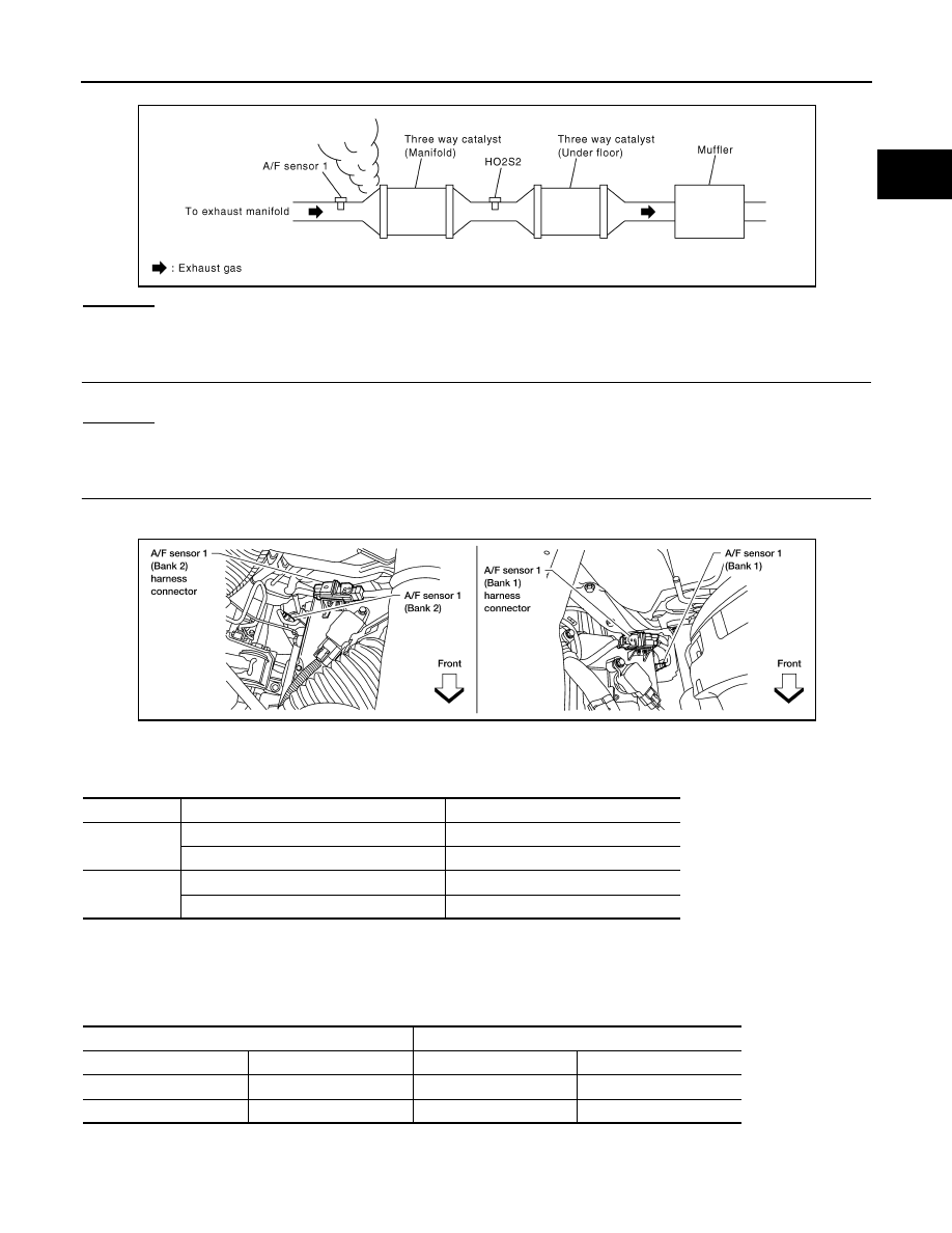
CHECK A/F SENSOR 1 INPUT SIGNAL CIRCUIT
1. Turn ignition switch OFF.
2. Disconnect corresponding A/F sensor 1 harness connector.
3. Disconnect ECM harness connector.
4. Check harness continuity between the following terminals.
Refer to Wiring Diagram.
5. Check harness continuity between the following terminals and ground.
Refer to Wiring Diagram.
6. Also check harness for short to power.
PBIB1216E
A/F sensor 1 terminal
ECM terminal
Bank 1
1
35
2
56
Bank 2
1
16
2
75
Continuity should exist.
Bank 1
Bank 2
A/F sensor 1 terminal
ECM terminal
A/F sensor 1 terminal
ECM terminal
1
35
1
16
2
56
2
75
Continuity should not exist.
BBIA0376E
Нет комментариевНе стесняйтесь поделиться с нами вашим ценным мнением.
Текст