Infiniti QX56 (JA60). Manual — part 438
EC-404
< COMPONENT DIAGNOSIS >
[VK56DE]
ICC BRAKE SWITCH
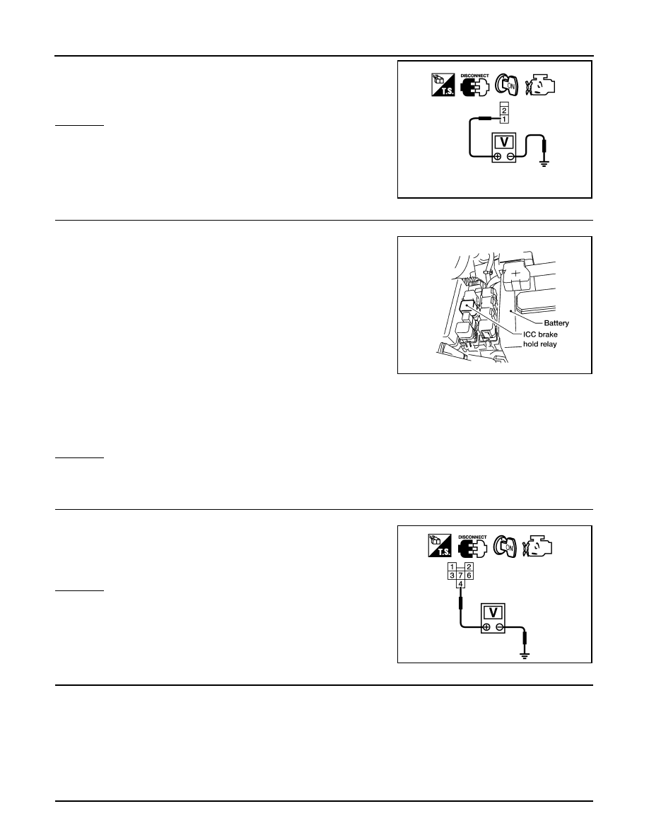
4. Check voltage between ICC brake switch terminal 1 and ground
with CONSULT-III or tester.
OK or NG
OK
>> GO TO 6.
NG
>> GO TO 3.
3.
CHECK ICC BRAKE SWITCH POWER SUPPLY CIRCUIT-II
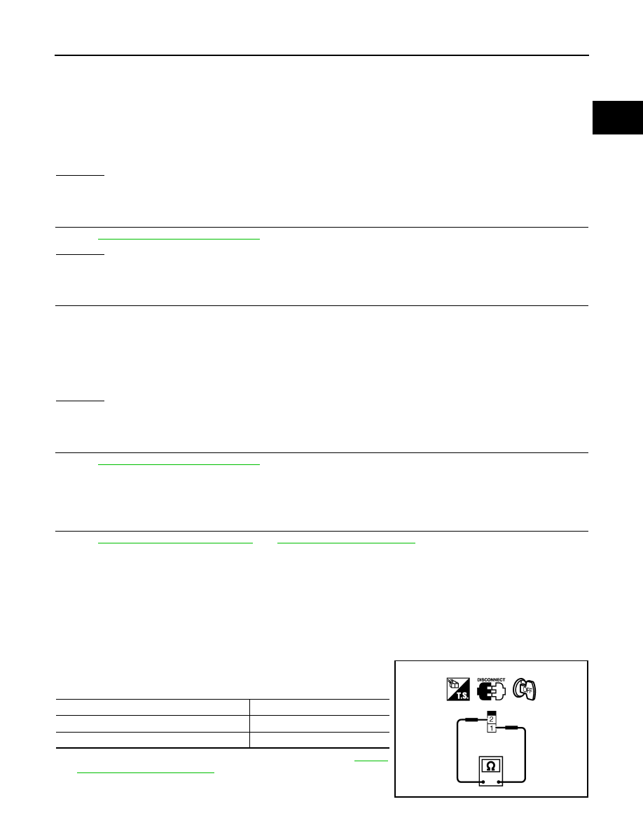
1. Turn ignition switch OFF.
2. Disconnect ICC brake hold relay.
3. Check harness continuity between ICC brake switch terminal 1 and ICC brake hold relay terminal 3.
Refer to Wiring Diagram
OK or NG
OK
>> GO TO 4.
NG
>> Repair open circuit or short to ground or short to power in harness or connectors.
4.
CHECK ICC BRAKE HOLD RELAY POWER SUPPLY CIRCUIT
1. Turn ignition switch ON.
2. Check the voltage between ICC brake hold relay terminal 4 and
ground with CONSULT-III or tester.
OK or NG
OK
>> GO TO 8.
NG
>> GO TO 5.
5.
DETECT MALFUNCTIONING PART
Check the following.
• Harness connectors M31, E152
• Fuse block (J/B) connector M4
• 10 A fuse (No.15)
• Harness for open or short between ICC brake hold relay and fuse
>> Repair open circuit or short to ground or short to power in harness or connectors.
6.
CHECK ICC BRAKE SWITCH INPUT SIGNAL CIRCUIT FOR OPEN AND SHORT
Voltage: Battery voltage
PBIB0857E
BBIA0471E
Continuity should exist.
Voltage: Battery voltage
MBIB0059E
ICC BRAKE SWITCH
EC-405
< COMPONENT DIAGNOSIS >
[VK56DE]
C
D
E
F
G
H
I
J
K
L
M
A
EC
N
P
O
1. Turn ignition switch OFF.
2. Disconnect ECM harness connector.
3. Check harness continuity between ICC brake switch terminal 2 and ECM terminal 108, ICC brake switch
terminal 2 and ICC unit terminal 29.
Refer Wiring Diagram.
4. Also check harness for short to ground and short to power.
OK or NG
OK
>> GO TO 7.
NG
>> Repair open circuit or short to ground or short to power in harness or connectors.
7.
CHECK ICC BRAKE SWITCH
EC-343, "Component Inspection"
OK or NG
OK
>> GO TO 10.
NG
>> Replace ICC brake switch.
8.
CHECK ICC BRAKE HOLD RELAY POWER SUPPLY AND GROUND CIRCUIT FOR OPEN AND SHORT
1. Check harness continuity between ICC brake hold relay terminal 1 and ICC unit terminal 47, ICC brake
hold relay terminal 2 and ground.
Refer to Wiring Diagram
2. Also check harness for short to ground or short to power in harness or connectors.
OK or NG
OK
>> GO TO 9.
NG
>> Repair or replace.
9.
CHECK ICC BRAKE HOLD RELAY
EC-343, "Component Inspection"
OK
>> GO TO 10.
NG
>> Replace ICC brake hold relay.
10.
CHECK INTERMITTENT INCIDENT
GI-35, "How to Check Terminal"
GI-38, "Intermittent Incident"
>> INSPECTION END
Component Inspection
INFOID:0000000005149481
ICC BRAKE SWITCH
1. Turn ignition switch OFF.
2. Disconnect ICC brake switch harness connector.
3. Check continuity between ICC brake switch terminals 1 and 2
under the following conditions.
If NG, adjust ICC brake switch installation, refer to
, and perform step 3 again.
Continuity should exist.
Continuity should exist
Condition
Continuity
Brake pedal: Fully released.
Should exist.
Brake pedal: Slightly depressed.
Should not exist.
PBIB1536E
EC-406
< COMPONENT DIAGNOSIS >
[VK56DE]
ICC BRAKE SWITCH
ICC BRAKE HOLD RELAY
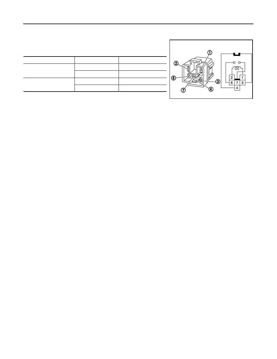
1. Apply 12V direct current between ICC brake hold relay terminals 1 and 2.
2. Check continuity between relay terminals 3 and 4, 6 and 7 under
the following conditions.
3. If NG, replace ICC brake hold relay.
Condition
Between terminals
Continuity
12 V direct current supply
between terminals 1 and 2
3 and 4
Should not exist
6 and 7
Should exist
No current supply
3 and 4
Should exist
6 and 7
Should not exist
MBIB0063E
IGNITION SIGNAL
EC-407
< COMPONENT DIAGNOSIS >
[VK56DE]
C
D
E
F
G
H
I
J
K
L
M
A
EC
N
P
O
IGNITION SIGNAL
Component Description
INFOID:0000000005149482
IGNITION COIL & POWER TRANSISTOR
The ignition signal from the ECM is sent to and amplified by the power transistor. The power transistor turns
ON and OFF the ignition coil primary circuit. This ON/OFF operation induces the proper high voltage in the coil
secondary circuit.
Diagnosis Procedure
INFOID:0000000005149483
1.
CHECK ENGINE START
Turn ignition switch OFF, and restart engine.
Is engine running?
Yes or No
Yes (With CONSULT-III)>>GO TO 2.
Yes (Without CONSULT-III)>>GO TO 3.
No
>> GO TO 4.
2.
CHECK OVERALL FUNCTION
With CONSULT-III
1. Perform “POWER BALANCE” in “ACTIVE TEST” mode with CONSULT-III.
2. Make sure that each circuit produces a momentary engine speed drop.
OK or NG
OK
>> INSPECTION END
NG
>> GO TO 10.
3.
CHECK OVERALL FUNCTION
Without CONSULT-III
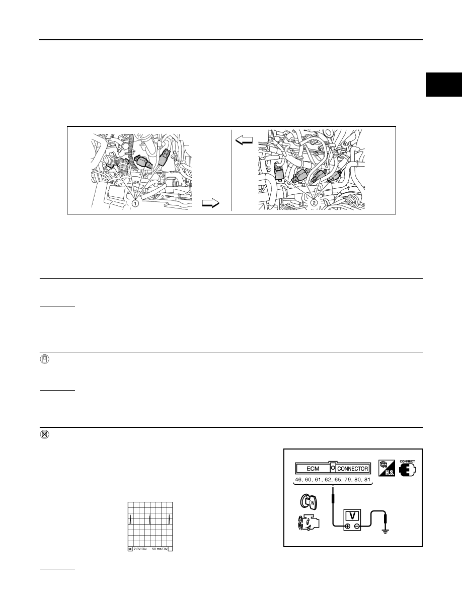
1. Let engine idle.
2. Read the voltage signal between ECM terminals 46, 60, 61, 62,
65, 79, 80, 81 and ground with an oscilloscope.
3. Verify that the oscilloscope screen shows the signal wave as
shown below.
NOTE:
The pulse cycle changes depending on rpm at idle.
OK or NG
1.
Ignition coils (with power transistor)
(bank 2)
2.
Ignition coils (with power transistor)
(bank 1)
BBIA0777E
PBIB2094E
PBIB0044E
Нет комментариевНе стесняйтесь поделиться с нами вашим ценным мнением.
Текст