Infiniti QX56 (JA60). Manual — part 436
EC-396
< COMPONENT DIAGNOSIS >
[VK56DE]
FUEL INJECTOR
FUEL INJECTOR
Component Description
INFOID:0000000005149473
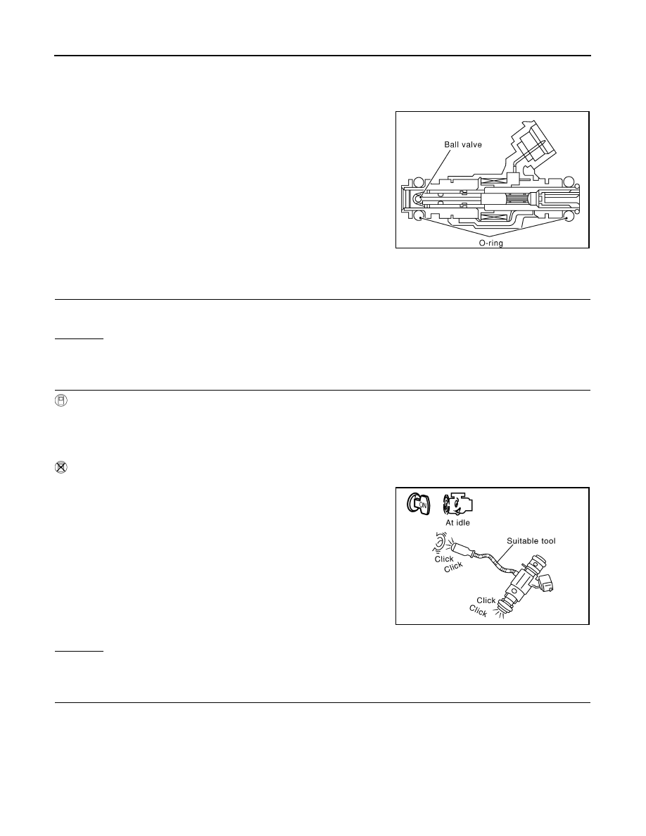
The fuel injector is a small, precise solenoid valve. When the ECM
supplies a ground to the fuel injector circuit, the coil in the fuel injec-
tor is energized. The energized coil pulls the ball valve back and
allows fuel to flow through the fuel injector into the intake manifold.
The amount of fuel injected depends upon the injection pulse dura-
tion. Pulse duration is the length of time the fuel injector remains
open. The ECM controls the injection pulse duration based on
engine fuel needs.
Diagnosis Procedure
INFOID:0000000005149474
1.
INSPECTION START
Turn ignition switch to START.
Is any cylinder ignited?
Yes or No
Yes
>> GO TO 2.
No
>> GO TO 3.
2.
CHECK OVERALL FUNCTION
With CONSULT-III
1. Start engine.
2. Perform “POWER BALANCE” in “ACTIVE TEST” mode with CONSULT-III.
3. Make sure that each circuit produces a momentary engine speed drop.
Without CONSULT-III
1. Start engine.
2. Listen to each fuel injector operating sound.
Clicking noise should be heard.
OK or NG
OK
>> INSPECTION END
NG
>> GO TO 3.
3.
CHECK FUEL INJECTOR POWER SUPPLY CIRCUIT
1. Turn ignition switch OFF.
SEF375Z
PBIB1986E
FUEL INJECTOR
EC-397
< COMPONENT DIAGNOSIS >
[VK56DE]
C
D
E
F
G
H
I
J
K
L
M
A
EC
N
P
O
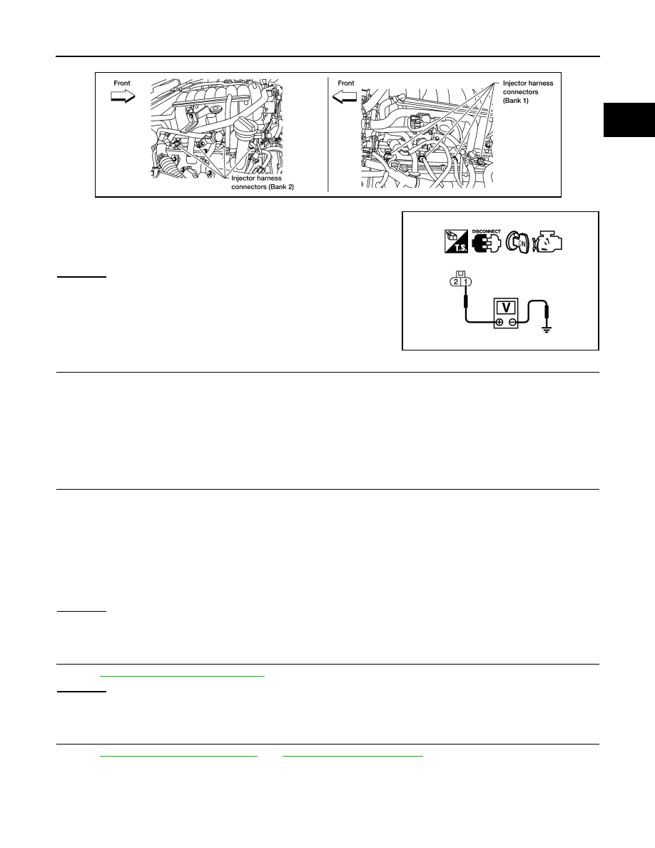
2. Disconnect fuel injector harness connector.
3. Turn ignition switch ON.
4. Check voltage between fuel injector terminal 1 and ground with
CONSULT-III or tester.
OK or NG
OK
>> GO TO 5.
NG
>> GO TO 4.
4.
DETECT MALFUNCTIONING PART
Check the following.
• Harness connectors E2, F32
• IPDM E/R connector E119
• 15 A fuse (No. 55)
• Harness for open or short between fuel injector and fuse
>> Repair harness or connectors.
5.
CHECK FUEL INJECTOR OUTPUT SIGNAL CIRCUIT FOR OPEN AND SHORT
1. Turn ignition switch OFF.
2. Disconnect ECM harness connector.
3. Check harness continuity between fuel injector terminal 2 and ECM terminals 21, 22, 23, 40, 41, 42, 44,
63.
Refer to Wiring Diagram.
4. Also check harness for short to ground and short to power.
OK or NG
OK
>> GO TO 6.
NG
>> Repair open circuit or short to ground or short to power in harness or connectors.
6.
CHECK FUEL INJECTOR
EC-398, "Component Inspection"
OK or NG
OK
>> GO TO 7.
NG
>> Replace malfunctioning fuel injector.
7.
CHECK INTERMITTENT INCIDENT
GI-35, "How to Check Terminal"
GI-38, "Intermittent Incident"
>> INSPECTION END
Voltage: Battery voltage
BBIA0374E
PBIB0582E
Continuity should exist.
EC-398
< COMPONENT DIAGNOSIS >
[VK56DE]
FUEL INJECTOR
Component Inspection
INFOID:0000000005149475
FUEL INJECTOR
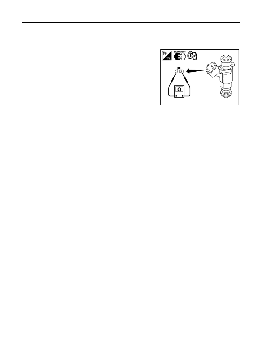
1. Disconnect fuel injector harness connector.
2. Check resistance between terminals as shown in the figure.
Resistance: 11.1 - 14.5
Ω [at 10 - 60°C (50 - 140°F)]
PBIB1727E
FUEL PUMP
EC-399
< COMPONENT DIAGNOSIS >
[VK56DE]
C
D
E
F
G
H
I
J
K
L
M
A
EC
N
P
O
FUEL PUMP
Description
INFOID:0000000005149476
SYSTEM DESCRIPTION
*: ECM determines the start signal status by the signals of engine speed and battery voltage.
The ECM activates the fuel pump for several seconds after the ignition switch is turned ON to improve engine
startability. If the ECM receives a engine speed signal from the camshaft position sensor (PHASE), it knows
that the engine is rotating, and causes the pump to operate. If the engine speed signal is not received when
the ignition switch is ON, the engine stalls. The ECM stops pump operation and prevents battery discharging,
thereby improving safety. The ECM does not directly drive the fuel pump. It controls the ON/OFF fuel pump
relay, which in turn controls the fuel pump.
COMPONENT DESCRIPTION
A turbine type design fuel pump is used in the fuel tank.
Diagnosis Procedure
INFOID:0000000005149477
1.
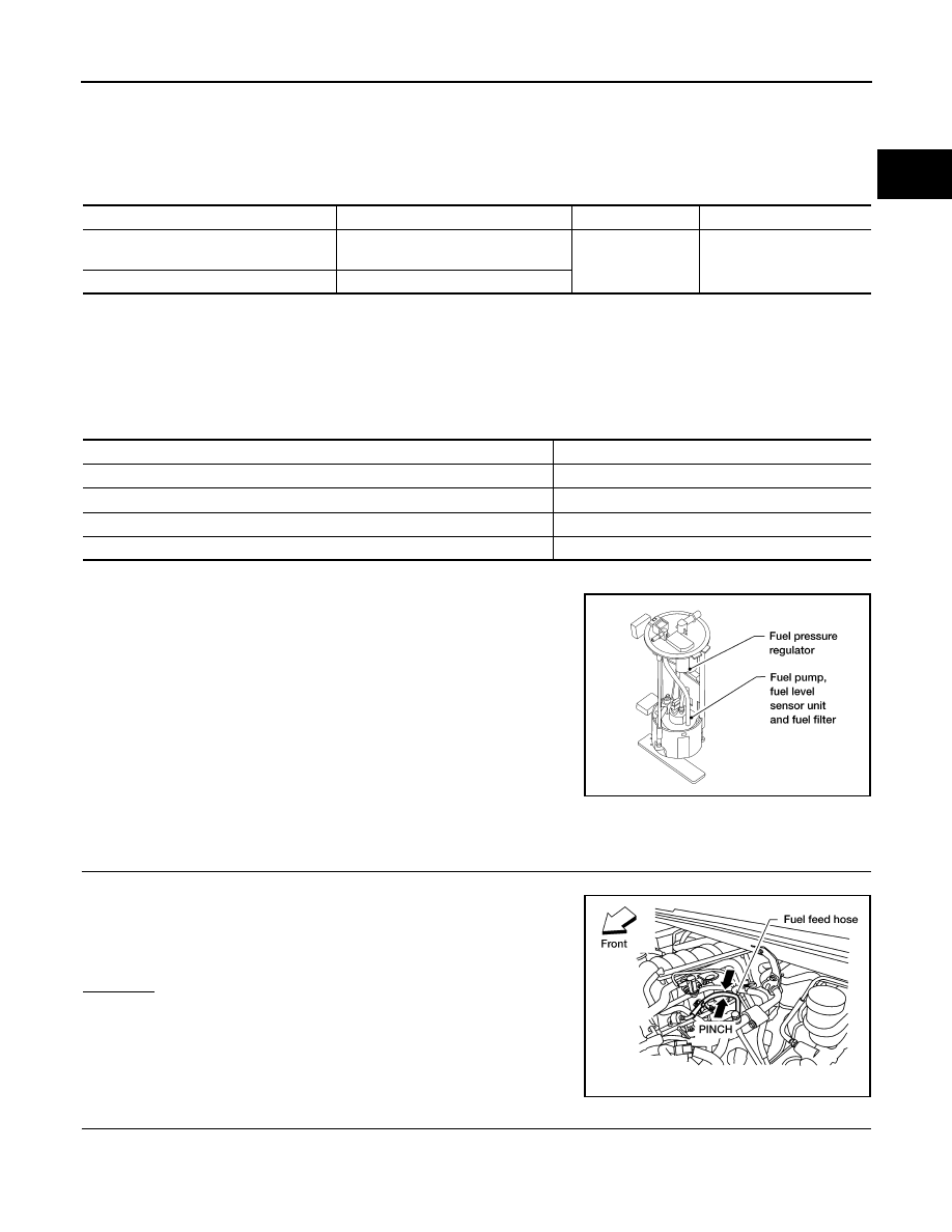
CHECK OVERALL FUNCTION
1. Turn ignition switch ON.
2. Pinch fuel feed hose with two fingers.
OK or NG
OK
>> INSPECTION END
NG
>> GO TO 2.
2.
CHECK FUEL PUMP POWER SUPPLY CIRCUIT-I
1. Turn ignition switch OFF.
2. Disconnect ECM harness connector.
3. Turn ignition switch ON.
Sensor
Input signal to ECM
ECM Function
Actuator
Crankshaft position sensor (POS)
Camshaft position sensor (PHASE)
Engine speed*
Fuel pump control
Fuel pump relay
Battery
Battery voltage*
Condition
Fuel pump operation
Ignition switch is turned to ON.
Operates for 1 second.
Engine running and cranking
Operates.
When engine is stopped
Stops in 1.5 seconds.
Except as shown above
Stops.
BBIA0402E
Fuel pressure pulsation should be felt on the fuel feed
hose for 1 second after ignition switch is turned ON.
BBIA0357E
Нет комментариевНе стесняйтесь поделиться с нами вашим ценным мнением.
Текст