Infiniti QX56 (JA60). Manual — part 366
EC-116
< COMPONENT DIAGNOSIS >
[VK56DE]
P0112, P0113 IAT SENSOR
OK or NG
OK
>> GO TO 2.
NG
>> Repair or replace ground connections.
2.
CHECK INTAKE AIR TEMPERATURE SENSOR POWER SUPPLY CIRCUIT
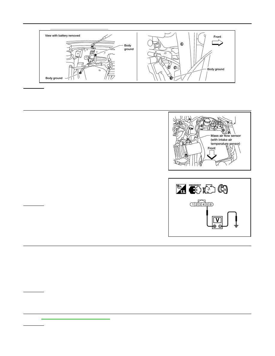
1. Disconnect mass air flow sensor (with intake air temperature
sensor) harness connector.
2. Turn ignition switch ON.
3. Check voltage between mass air flow sensor terminal 5 and
ground.
OK or NG
OK
>> GO TO 3.
NG
>> Repair harness or connectors.
3.
CHECK INTAKE AIR TEMPERATURE SENSOR GROUND CIRCUIT FOR OPEN AND SHORT
1. Turn ignition switch OFF.
2. Disconnect ECM harness connector.
3. Check harness continuity between mass air flow sensor terminal 6 and ECM terminal 67.
Refer to Wiring Diagram.
4. Also check harness for short to ground and short to power.
OK or NG
OK
>> GO TO 4.
NG
>> Repair open circuit or short to ground or short to power in harness or connectors.
4.
CHECK INTAKE AIR TEMPERATURE SENSOR
EC-117, "Component Inspection"
.
OK or NG
OK
>> GO TO 5.
NG
>> Replace mass air flow sensor (with intake air temperature sensor).
BBIA0354E
BBIA0368E
Voltage: Approximately 5 V
PBIB1169E
Continuity should exist.
P0112, P0113 IAT SENSOR
EC-117
< COMPONENT DIAGNOSIS >
[VK56DE]
C
D
E
F
G
H
I
J
K
L
M
A
EC
N
P
O
5.
CHECK INTERMITTENT INCIDENT
GI-35, "How to Check Terminal"
GI-38, "Intermittent Incident"
>> INSPECTION END
Component Inspection
INFOID:0000000005149125
INTAKE AIR TEMPERATURE SENSOR
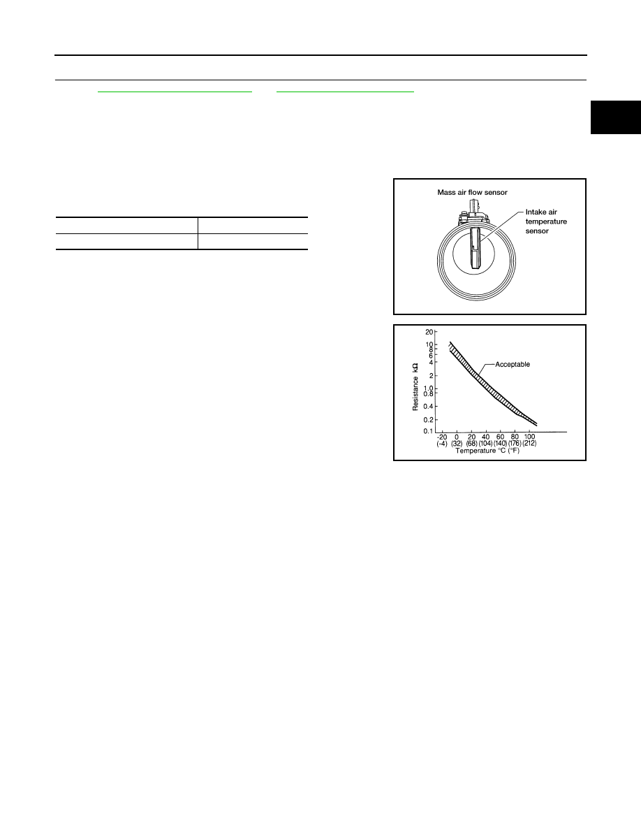
1. Check resistance between mass air flow sensor terminals 5 and
6 under the following conditions.
2. If NG, replace mass air flow sensor (with intake air temperature
sensor).
Intake air temperature
°C (°F)]
Resistance (k
Ω)
25 (77)
1.800 - 2.200
BBIA0355E
SEF012P
EC-118
< COMPONENT DIAGNOSIS >
[VK56DE]
P0116 ECT SENSOR
P0116 ECT SENSOR
Component Description
INFOID:0000000005149126
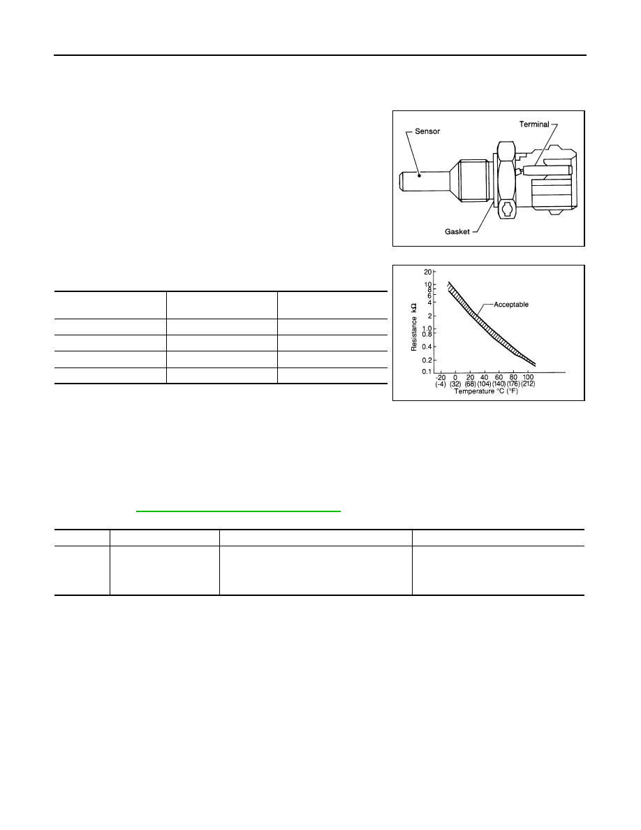
The engine coolant temperature sensor is used to detect the engine
coolant temperature. The sensor modifies a voltage signal from the
ECM. The modified signal returns to the ECM as the engine coolant
temperature input. The sensor uses a thermistor which is sensitive to
the change in temperature. The electrical resistance of the ther-
mistor decreases as temperature increases.
<Reference data>
*: This data is reference value and is measured between ECM terminal 73 (Engine
coolant temperature sensor) and ground.
CAUTION:
Do not use ECM ground terminals when measuring input/output voltage. Doing so may result in dam-
age to the ECM's transistor. Use a ground other than ECM terminals, such as the ground.
On Board Diagnosis Logic
INFOID:0000000005149127
NOTE:
If DTC P0116 is displayed with P0117 or P0118, first perform the trouble diagnosis for DTC P0117,
P0118. Refer to
EC-122, "DTC Confirmation Procedure"
.
DTC Confirmation Procedure
INFOID:0000000005149128
NOTE:
If DTC Confirmation Procedure has been previously conducted, always perform the following procedure
before conducting the next step.
• Turn ignition switch OFF and wait at least 10 seconds.
• Turn ignition switch ON.
• Turn ignition switch OFF and wait at least 10 seconds.
TESTING CONDITION:
Before performing the following procedure, do not fill with the fuel.
1. Start engine and warm it up to normal operating temperature.
2. Rev engine up to 2,000 rpm for more than10 minutes.
3. Move the vehicle to a cool place, then stop engine and turn ignition switch OFF.
4. Check resistance between “fuel level sensor and fuel pump” terminals 3 and 4.
SEF594K
Engine coolant
temperature
°C (°F)]
Voltage* (V)
Resistance (k
Ω)
−10 (14)
4.4
7.0 - 11.4
20 (68)
3.5
2.1 - 2.9
50 (122)
2.2
0.68 - 1.00
90 (194)
0.9
0.236 - 0.260
SEF012P
DTC No.
Trouble diagnosis name
DTC detecting condition
Possible cause
P0116
0116
Engine coolant tempera-
ture sensor circuit range/
performance
Engine coolant temperature signal from engine
coolant temperature sensor does not fluctuate,
even when some time has passed after starting
the engine with pre-warming up condition.
• Harness or connectors
(High or low resistance in the circuit)
• Engine coolant temperature sensor
P0116 ECT SENSOR
EC-119
< COMPONENT DIAGNOSIS >
[VK56DE]
C
D
E
F
G
H
I
J
K
L
M
A
EC
N
P
O
5. Soak the vehicle until the resistance between “fuel level sensor and fuel pump” terminals 3 and 4
becomes 0.5 k
Ω higher than the value measured before soaking.
CAUTION:
Never turn ignition switch ON during the soaking time.
NOTE:
Soak time changes depending on ambient air temperature. It may take several hours.
6. Start engine and let it idle for 5 minutes.
7. Check 1st trip DTC.
8. If 1st trip DTC is detected, go to
Diagnosis Procedure
INFOID:0000000005149129
1.
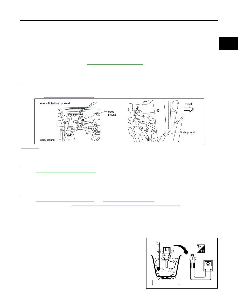
CHECK GROUND CONNECTIONS
1. Turn ignition switch OFF.
2. Loosen and retighten three ground screws on the body.
OK or NG
OK
>> GO TO 2.
NG
>> Repair or replace ground connections.
2.
CHECK ENGINE COOLANT TEMPERATURE SENSOR
EC-119, "Component Inspection"
.
OK or NG
OK
>> GO TO 3.
NG
>> Replace engine coolant temperature sensor.
3.
CHECK INTERMITTENT INCIDENT
GI-35, "How to Check Terminal"
GI-38, "Intermittent Incident"
For Wiring Diagram, refer to
EC-435, "Wiring Diagram - ENGINE CONTROL SYSTEM -"
.
>> INSPECTION END
Component Inspection
INFOID:0000000005149130
ENGINE COOLANT TEMPERATURE SENSOR
1. Check resistance between engine coolant temperature sensor
terminals 1 and 2 as shown in the figure.
BBIA0354E
PBIB2005E
Нет комментариевНе стесняйтесь поделиться с нами вашим ценным мнением.
Текст