Infiniti QX56 (JA60). Manual — part 503
PARKING LAMP CIRCUIT
EXL-41
< COMPONENT DIAGNOSIS >
C
D
E
F
G
H
I
J
K
M
A
B
EXL
N
O
P
3. Check continuity between the license plate lamp harness con-
nectors and ground.
Does continuity exist?
YES
>> Inspect the parking lamp bulb.
NO
>> Repair the harness.
Diagnosis Procedure - With Daytime Light System
INFOID:0000000005146653
Regarding Wiring Diagram information, refer to
.
1.
CHECK PARKING LAMP FUSES
1. Turn the ignition switch OFF.
2. Check that the following fuses are not open.
Is the fuse open?
YES
>> Repair the harness and replace the fuse.
NO
>> GO TO 2.
2.
CHECK TAIL LAMP RELAY OUTPUT (VOLTAGE)
1. Turn the ignition switch OFF.
2. Disconnect the front combination lamp connector, rear combination lamp connector and license plate
lamp connector.
3. Turn the ignition switch ON.
4. Turn the parking lamps ON.
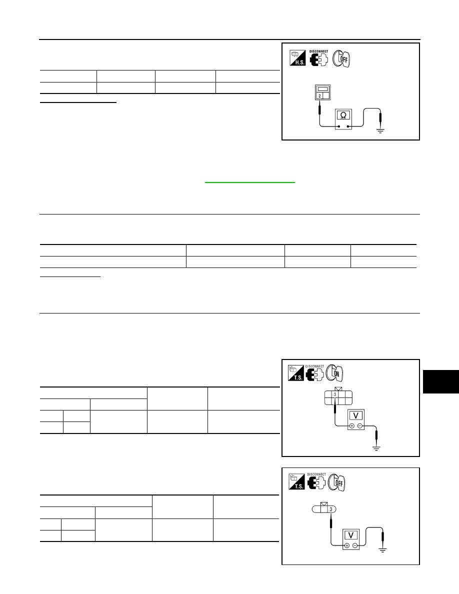
5. With the parking lamps ON, check voltage between the front
combination lamp connectors and ground.
6. With the parking lamps ON, check voltage between the rear
combination lamp connectors and ground.
Connector
Terminal
—
Continuity
D703
2
Ground
Yes
WKIA4615E
Unit
Location
Fuse No.
Capacity
Parking lamps
IPDM E/R
37
10A
(+)
(
−)
Voltage
Connector
Terminal
LH
E6
3
Ground
Battery voltage
RH
E108
ALLIA0857ZZ
(+)
(
−)
Voltage
Connector
Terminal
LH
B70
3
Ground
Battery voltage
RH
B130
AWLIA1622ZZ
EXL-42
< COMPONENT DIAGNOSIS >
PARKING LAMP CIRCUIT
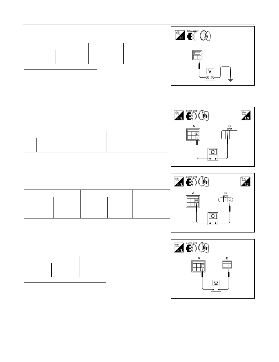
7. With the parking lamps ON, check voltage between the license
plate lamp connector and ground
Are voltage readings as specified?
YES
>> GO TO 4.
NO
>> GO TO 3.
3.
CHECK PARKING, LICENSE PLATE AND TAIL LAMP CIRCUIT (OPEN)
1. Turn the ignition switch OFF.
2. Disconnect IPDM E/R connector.
3. Check continuity between the IPDM E/R harness connector (A)
and the front combination lamp harness connector (B).
4. Check continuity between the IPDM E/R harness connector (A)
and the rear combination lamp harness connector (B).
5. Check continuity between the IPDM E/R harness connector (A)
and license plate lamp connector (B).
Are continuity test results as specified?
YES
>> GO TO 4.
NO
>> Repair the harnesses or connectors.
4.
CHECK PARKING, LICENSE AND TAIL LAMP GROUND CIRCUITS
(+)
(
−)
Voltage
Connector
Terminal
D703
1
Ground
Battery voltage
WKIA4613E
A
B
Continuity
Connector
Terminal
Connector
Terminal
LH
E124
57
E6
3
Yes
RH
E108
AWLIA1373ZZ
A
B
Continuity
Connector
Terminal
Connector
Terminal
LH
E124
57
B70
3
Yes
RH
B130
AWLIA1623ZZ
A
B
Continuity
Connector
Terminal
Connector
Terminal
E124
57
D703
1
Yes
WKIA4614E
PARKING LAMP CIRCUIT
EXL-43
< COMPONENT DIAGNOSIS >
C
D
E
F
G
H
I
J
K
M
A
B
EXL
N
O
P
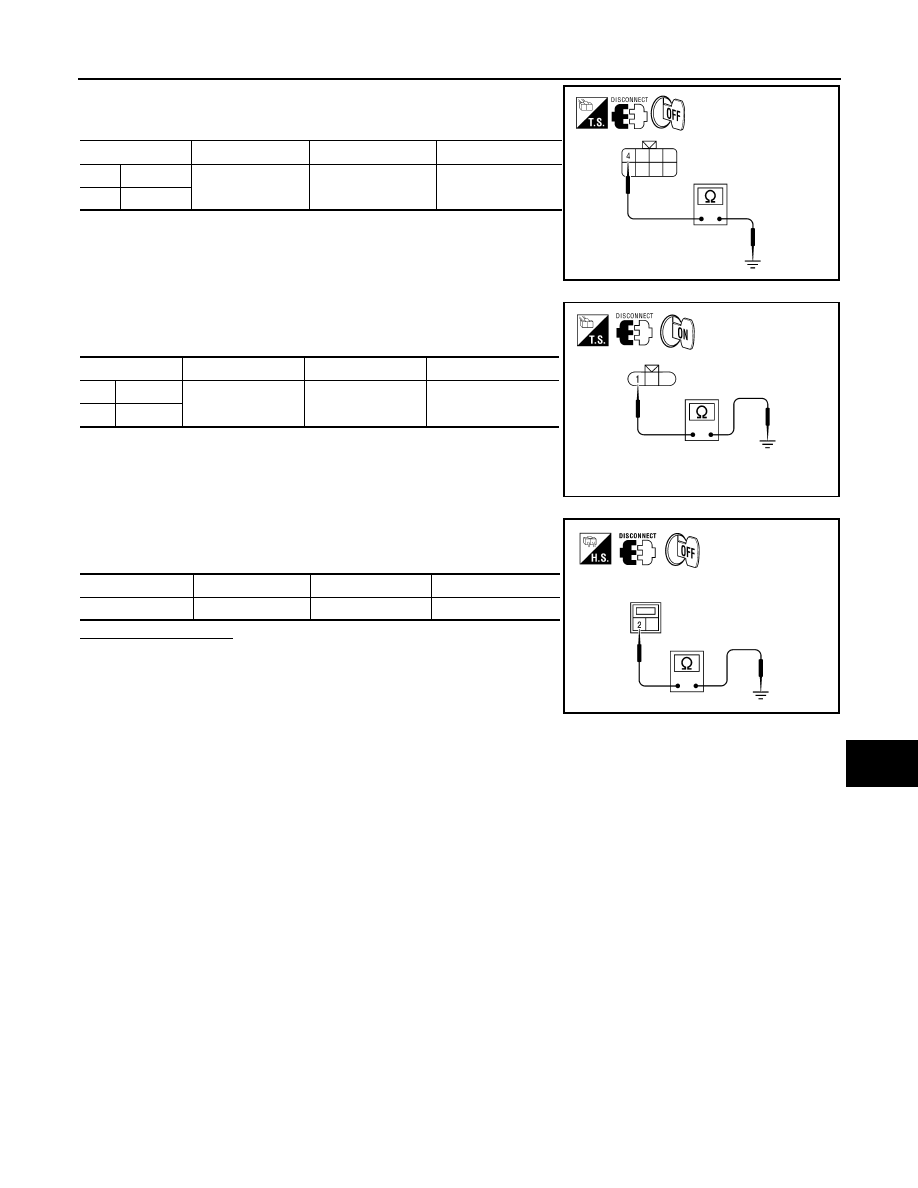
1. Check continuity between the front combination lamp harness
connectors E6 and E108 terminal 4 and ground.
2. Check continuity between the rear combination lamp harness
connectors B70 and B130 terminal 1 and ground.
3. Check continuity between the license plate lamp harness con-
nectors and ground.
Does continuity exist?
YES
>> Inspect the parking lamp bulb.
NO
>> Repair the harness.
Connector
Terminal
—
Continuity
LH
E6
4
Ground
Yes
RH
E108
AWLIA1619ZZ
Connector
Terminal
—
Continuity
LH
B70
1
Ground
Yes
RH
B130
AWLIA1624ZZ
Connector
Terminal
—
Continuity
D703
2
Ground
Yes
WKIA4615E
EXL-44
< COMPONENT DIAGNOSIS >
TURN SIGNAL LAMP CIRCUIT
TURN SIGNAL LAMP CIRCUIT
Description
INFOID:0000000005146654
The BCM monitors inputs from the combination switch (lighting and turn signal switch) to determine when to
activate the turn signals. The BCM outputs voltage direction to the left and right turn signals during turn signal
operation or both during hazard warning operation. The BCM sends a turn signal indicator request to the com-
bination meter via the CAN communication lines.
The BCM performs the fast flasher operation (fail-safe) if any bulb or harness of the turn signal lamp circuit is
open.
NOTE:
Turn signal lamp blinks at normal speed when using the hazard warning lamp.
Component Function Check
INFOID:0000000005146655
1.
CHECK TURN SIGNAL LAMP
CONSULT-III
1. Select "FLASHER" of BCM (FLASHER) active test item.
2. With operating the test items, check that the turn signal lamp blinks.
Does the turn signal lamp blink?
YES
>> Turn signal lamp circuit is normal.
NO
>> Refer to
.
Diagnosis Procedure
INFOID:0000000005146656
Regarding Wiring Diagram information, refer to
1.
CHECK TURN SIGNAL LAMP BULB
Check the applicable lamp bulb to be sure the proper bulb standard is in use and the bulb is not open.
Is the bulb OK?
YES
>> GO TO 2.
NO
>> Replace the bulb.
2.
CHECK TURN SIGNAL LAMP OUTPUT VOLTAGE
1. Turn the ignition switch OFF.
2. Disconnect the front turn/fog lamp connector or the rear combi-
nation lamp connector.
3. Turn the ignition switch ON.
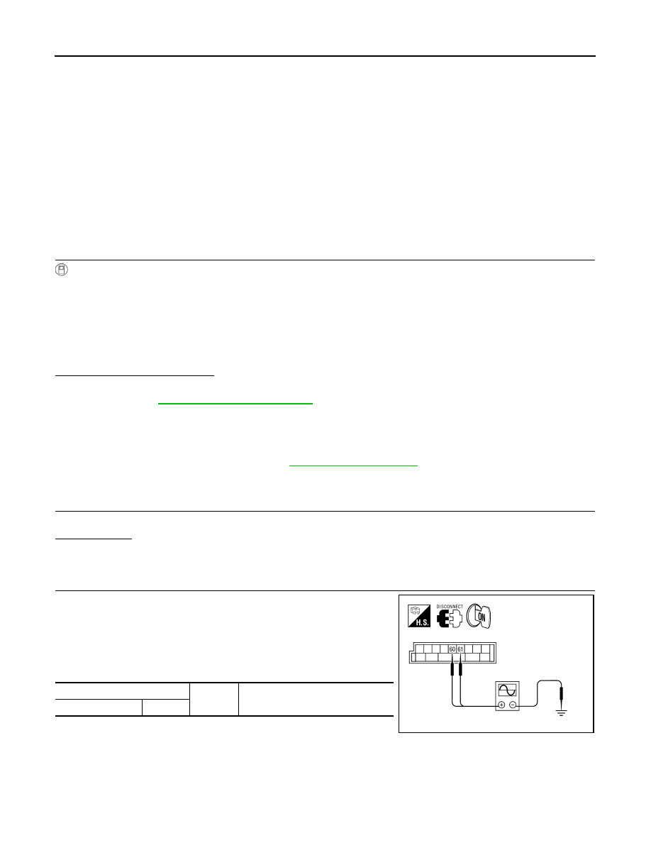
4. With turn signal switch operating, check the voltage between the
BCM harness connector M20 and ground.
LH
: Turn signal lamp LH blinking
RH
: Turn signal lamp RH blinking
Off
: The turn signal lamp OFF
(+)
(
−)
Voltage
Connector
Terminal
ALLIA0896ZZ
Нет комментариевНе стесняйтесь поделиться с нами вашим ценным мнением.
Текст