Infiniti QX56 (JA60). Manual — part 501
HEADLAMP (LO) CIRCUIT
EXL-33
< COMPONENT DIAGNOSIS >
C
D
E
F
G
H
I
J
K
M
A
B
EXL
N
O
P
HEADLAMP (LO) CIRCUIT
Description
INFOID:0000000005146643
The IPDM E/R (intelligent power distribution module engine room) controls the headlamp low relay based on
inputs from the BCM via the CAN communication lines. When the headlamp low relay is energized, power
flows through fuses 40 and 41, located in the IPDM E/R. Power then flows to the front combination lamps to
the headlamp low beam.
Component Function Check
INFOID:0000000005146644
1.
CHECK HEADLAMP (LO) OPERATION
WITHOUT CONSULT-III
1. Start IPDM E/R auto active test. Refer to
PCS-12, "Diagnosis Description"
2. Check that the headlamp is turned ON.
NOTE:
HI/LO is repeated 1 second each when using the IPDM E/R auto active test.
CONSULT-III
1. Select "EXTERNAL LAMPS" of IPDM E/R active test item.
2. With the test items operating, check that the headlamp is turned ON.
Is the headlamp turned ON?
YES
>> Headlamp (LO) is normal.
NO
>> Refer to
EXL-33, "Diagnosis Procedure - Without Daytime Light System"
,
Procedure - With Daytime Light System"
Diagnosis Procedure - Without Daytime Light System
INFOID:0000000005146645
Regarding Wiring Diagram information, refer to
.
1.
CHECK HEADLAMP (LO) FUSES
1. Turn the ignition switch OFF.
2. Check that the following fuses are not open.
Is the fuse open?
YES
>> Repair the harness and replace the fuse.
NO
>> GO TO 2.
2.
CHECK HEADLAMP (LO) OUTPUT VOLTAGE
Lo
: Headlamp ON
Off
: Headlamp OFF
Unit
Location
Fuse No.
Capacity
Headlamp LO (LH)
IPDM E/R
40
15A
Headlamp LO (RH)
IPDM E/R
41
15A
EXL-34
< COMPONENT DIAGNOSIS >
HEADLAMP (LO) CIRCUIT
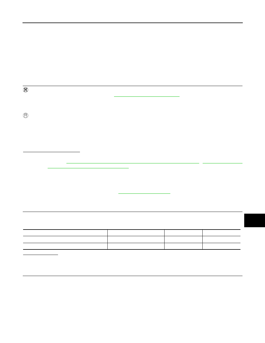
1. Turn the ignition switch OFF.
2. Disconnect the front combination lamp connector.
3. Turn the ignition switch ON.
4. Turn the low beam headlamps ON.
5. With the low beam headlamps ON, check the voltage between
the combination lamp connector and ground.
Is voltage reading as specified?
YES
>> GO TO 4.
NO
>> GO TO 3.
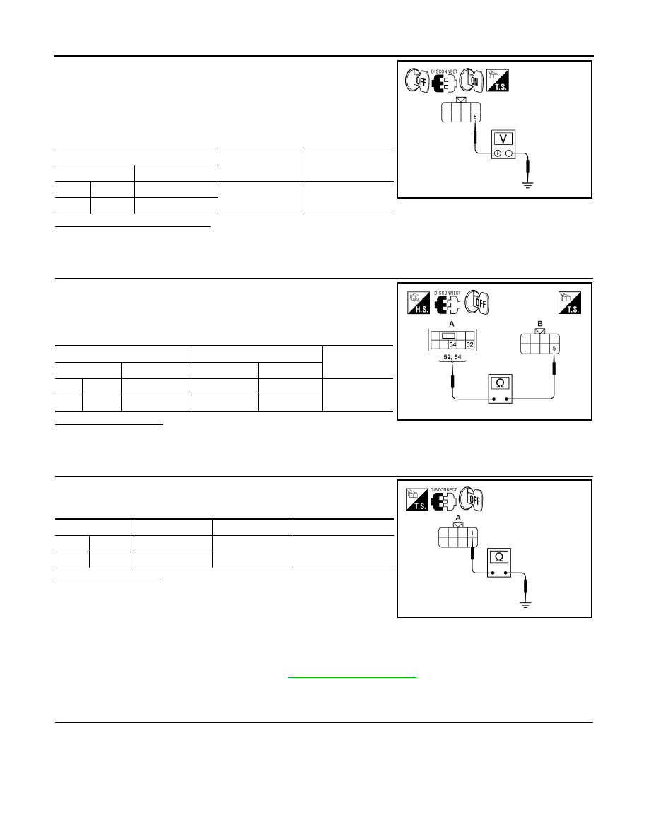
3.
CHECK HEADLAMP (LO) CIRCUIT FOR OPEN
1. Turn the ignition switch OFF.
2. Disconnect IPDM E/R connector.
3. Check continuity between the IPDM E/R harness connector and
the front combination lamp harness connector.
Does continuity exist?
YES
>> GO TO 4.
NO
>> Repair the harnesses or connectors.
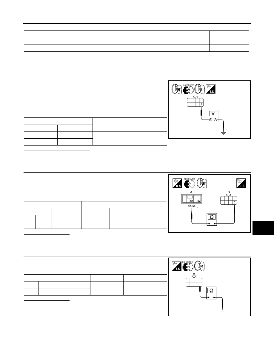
4.
CHECK FRONT COMBINATION LAMP (LO) GROUND CIRCUIT
Check continuity between the front combination lamp harness con-
nector terminal and ground.
Does continuity exist?
YES
>> Inspect the headlamp bulb.
NO
>> Repair the harness.
Diagnosis Procedure - With Daytime Light System
INFOID:0000000005146646
Regarding Wiring Diagram information, refer to
1.
CHECK HEADLAMP (LO) FUSES
1. Turn the ignition switch OFF.
2. Check that the following fuses are not open.
(+)
(
−)
Voltage
Connector
Terminal
LH
E11
5
Ground
Battery voltage
RH
E107
5
ALLIA0855ZZ
A
B
Continuity
Connector
Terminal
Connector
Terminal
LH
E123
52
E11
5
Yes
RH
54
E107
5
AWLIA1372ZZ
Connector
Terminal
—
Continuity
LH
E11
1
Ground
Yes
RH
E107
1
ALLIA0856ZZ
HEADLAMP (LO) CIRCUIT
EXL-35
< COMPONENT DIAGNOSIS >
C
D
E
F
G
H
I
J
K
M
A
B
EXL
N
O
P
Is the fuse open?
YES
>> Repair the harness and replace the fuse.
NO
>> GO TO 2.
2.
CHECK HEADLAMP (LO) OUTPUT VOLTAGE
1. Turn the ignition switch OFF.
2. Disconnect the front combination lamp connector.
3. Turn the ignition switch ON.
4. Turn the low beam headlamps ON.
5. With the low beam headlamps ON, check the voltage between
the combination lamp connector and ground.
Is voltage reading as specified?
YES
>> GO TO 4.
NO
>> GO TO 3.
3.
CHECK HEADLAMP (LO) CIRCUIT FOR OPEN
1. Turn the ignition switch OFF.
2. Disconnect IPDM E/R connector.
3. Check continuity between the IPDM E/R harness connector and
the front combination lamp harness connector.
Does continuity exist?
YES
>> GO TO 4.
NO
>> Repair the harnesses or connectors.
4.
CHECK FRONT COMBINATION LAMP (LO) GROUND CIRCUIT
Check continuity between the front combination lamp harness con-
nector terminal and ground.
Does continuity exist?
YES
>> Inspect the headlamp bulb.
NO - RH>>Repair the harness.
NO - LH>>Inspect the daytime light relay. If OK, repair harness. If
NG, replace the daytime light relay.
Unit
Location
Fuse No.
Capacity
Headlamp LO (LH)
IPDM E/R
40
15A
Headlamp LO (RH)
IPDM E/R
41
15A
(+)
(
−)
Voltage
Connector
Terminal
LH
E6
5
Ground
Battery voltage
RH
E108
5
ALLIA0855ZZ
A
B
Continuity
Connector
Terminal
Connector
Terminal
LH
E123
52
E6
5
Yes
RH
54
E108
5
AWLIA1372ZZ
Connector
Terminal
—
Continuity
LH
E6
1
Ground
Yes
RH
E108
1
ALLIA0856ZZ
EXL-36
< COMPONENT DIAGNOSIS >
FRONT FOG LAMP CIRCUIT
FRONT FOG LAMP CIRCUIT
Description
INFOID:0000000005146647
The IPDM E/R (intelligent power distribution module engine room) controls the front fog lamp relay based on
inputs from the BCM via the CAN communication lines. When the front fog lamp relay is energized, power
flows from the front fog lamp relay in the IPDM E/R to the front fog lamps.
Component Function Check
INFOID:0000000005146648
1.
CHECK FRONT FOG LAMP OPERATION
WITHOUT CONSULT-III
1. Activate IPDM E/R auto active test. Refer to
PCS-12, "Diagnosis Description"
2. Check that the front fog lamp is turned ON.
CONSULT-III
1. Select "EXTERNAL LAMPS" of IPDM E/R active test item.
2. With operating the test items, Check that the front fog lamp is turned ON.
Is the front fog lamp turned ON?
YES
>> Front fog lamp circuit is normal.
NO
>> Refer to
.
Diagnosis Procedure
INFOID:0000000005146649
Regarding Wiring Diagram information, refer to
1.
CHECK FRONT FOG LAMP FUSE
1. Turn the ignition switch OFF.
2. Check that the following fuses are not open.
Is the fuse open?
YES
>> Repair the harness and replace the fuse.
NO
>> GO TO 2.
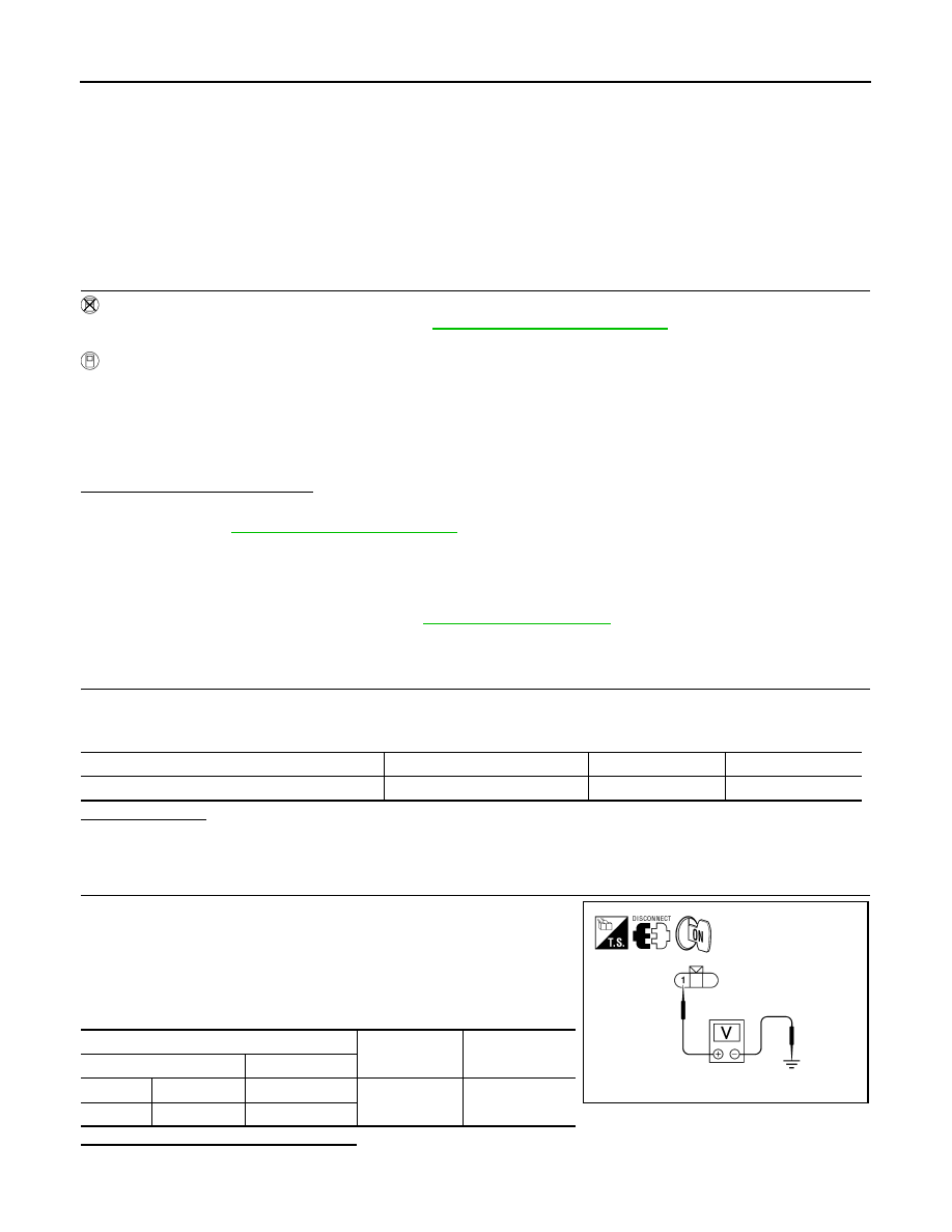
2.
CHECK FRONT FOG LAMP OUTPUT VOLTAGE
1. Turn the ignition switch OFF.
2. Disconnect the front fog/turn lamp connector.
3. Turn the ignition switch ON.
4. Turn the front fog lamps ON.
5. Check the voltage between the fog/turn lamp connector and
ground.
Are the voltage readings as specified?
YES
>> GO TO 4.
NO
>> GO TO 3.
Fog
: Front fog lamp ON
Off
: Front fog lamp OFF
Unit
Location
Fuse No.
Capacity
Front fog lamp
IPDM E/R
56
20A
(+)
(
−)
Voltage
Connector
Terminal
LH
E101
1
Ground
Battery voltage
RH
E102
1
ALLIA0719GB
Нет комментариевНе стесняйтесь поделиться с нами вашим ценным мнением.
Текст