Infiniti QX56 (JA60). Manual — part 275
P1811 POWER SUPPLY CIRCUIT FOR TRANSFER CONTROL UNIT
DLN-23
< COMPONENT DIAGNOSIS >
[ATX14B]
C
E
F
G
H
I
J
K
L
M
A
B
DLN
N
O
P
Are the inspection results normal?
YES
>> GO TO 2.
NO
>> Check the following. If any items are damaged, repair or replace damaged parts.
• 10A fuses No. 26 located in fuse and fusible link box and No. 59 located in the fuse and relay
box.
• 20A fuse No. 53 located in the IPDM E/R.
• Harness for short or open between battery and transfer control unit harness connector terminals
47.
• Harness for short or open between battery and transfer control unit harness connector terminal
29.
• Harness for short or open between battery and transfer shut off relay harness connector E69
terminal 1, and 5.
• Harness for short or open between transfer shut off relay harness connector E69 terminal 2 and
transfer control unit harness connector terminal 30.
• Harness for short or open between transfer shut off relay harness connector E69 terminal 3 and
transfer control unit harness connector terminals 16 and 22.
• Battery and ignition switch.
• Transfer shut off relay. Refer to
DLN-23, "Component Inspection"
2.
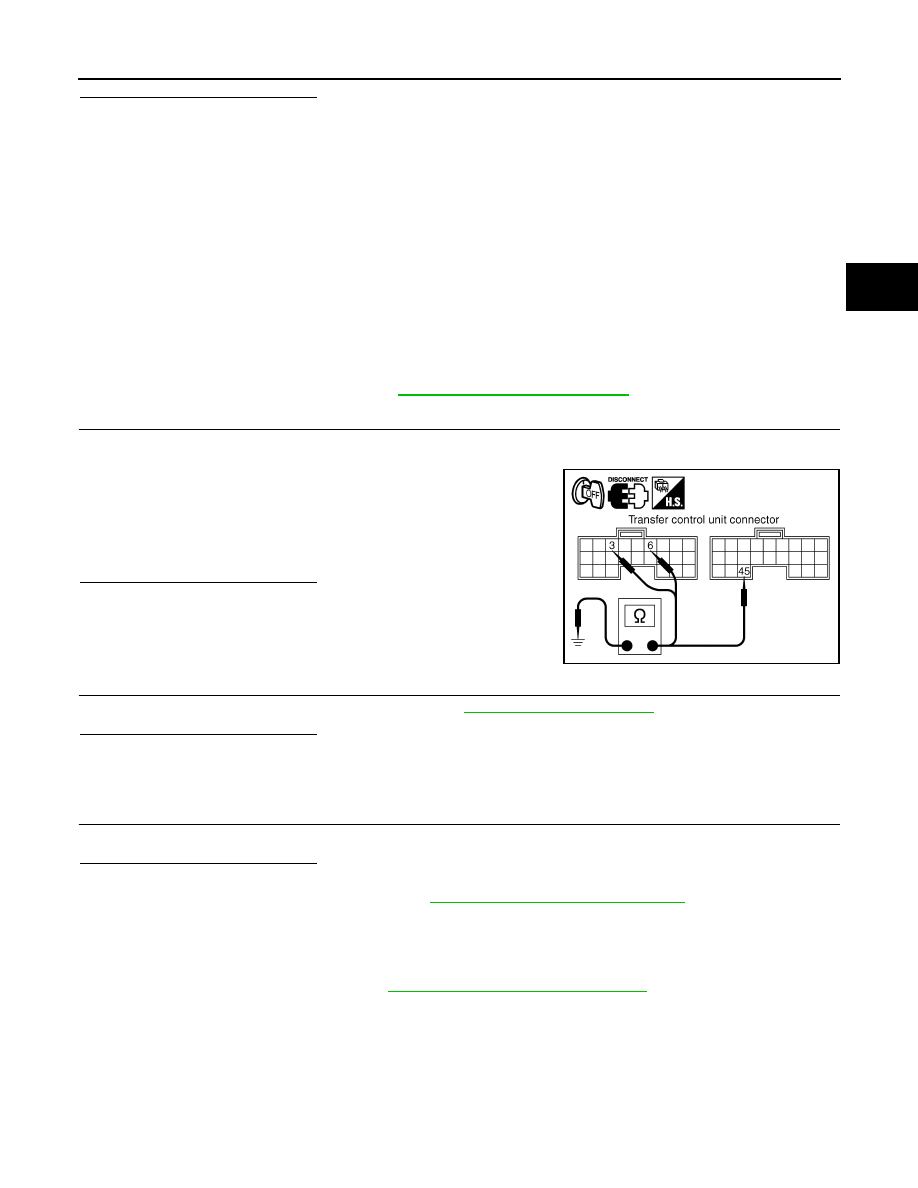
CHECK GROUND CIRCUIT
1. Turn ignition switch OFF. (Stay for at least 5 seconds.)
2. Disconnect transfer control unit harness connector.
3. Check continuity between transfer control unit harness connec-
tor E142 terminals 3, 6, E143 terminal 45 and ground.
Also check harness for short to ground and short to power.
Are the inspection results normal?
YES
>> GO TO 3.
NO
>> Repair open circuit or short to ground or short to power
in harness or connectors.
3.
CHECK TRANSFER CONTROL UNIT
Check transfer control unit input/output signal. Refer to
Are the inspection results normal?
YES
>> GO TO 4.
NO
>> Check transfer control unit pin terminals for damage or loose connection with harness connector.
If any items are damaged, repair or replace damaged parts.
4.
CHECK DTC
Perform the self-diagnosis, after driving a vehicle for a while.
Are the inspection results normal?
YES
>> Inspection End.
NO
>> Replace transfer control unit. Refer to
DLN-130, "Removal and Installation"
Component Inspection
INFOID:0000000005148778
1. Turn ignition switch OFF. (Stay for at least 5 seconds.)
2. Remove transfer shut off relay. Refer to
DLN-16, "Component Parts Location"
.
Continuity should exist.
SDIA2691E
DLN-24
< COMPONENT DIAGNOSIS >
[ATX14B]
P1811 POWER SUPPLY CIRCUIT FOR TRANSFER CONTROL UNIT
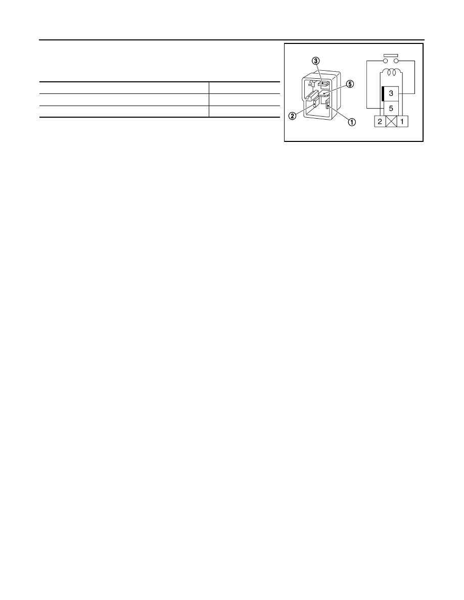
3. Apply 12V direct current between transfer shut off relay termi-
nals 1 and 2.
4. Check continuity between relay terminals 3 and 5.
5. If inspection results are abnormal replace the transfer shut off
relay.
Condition
Continuity
12V direct current supply between terminals 1 and 2
Yes
OFF
No
SCIA1245E
P1802 – P1804, P1809 TRANSFER CONTROL UNIT
DLN-25
< COMPONENT DIAGNOSIS >
[ATX14B]
C
E
F
G
H
I
J
K
L
M
A
B
DLN
N
O
P
P1802 – P1804, P1809 TRANSFER CONTROL UNIT
Description
INFOID:0000000005148779
The transfer control unit controls the transfer control device which controls shifts between AUTO, 4H and 4LO
and between 2WD and 4WD. A DTC may set when any of the following occur:
• Malfunction is detected in the memory (RAM) system of transfer control unit.
• Malfunction is detected in the memory (ROM) system of transfer control unit.
• Malfunction is detected in the memory (EEPROM) system of transfer control unit.
• AD converter system of transfer control unit is malfunctioning.
DTC Logic
INFOID:0000000005148780
DTC DETECTION LOGIC
DTC CONFIRMATION PROCEDURE
1.
DTC CONFIRMATION PROCEDURE
1. Turn ignition switch ON.
2. Perform self-diagnosis.
Are DTC's P1802 - P1804 or P1809 detected?
YES
>> Perform diagnosis procedure. Refer to
.
NO
>> Inspection End.
Diagnosis Procedure
INFOID:0000000005148781
1.
INSPECTION START
Do you have CONSULT-III?
YES or NO
YES
>> GO TO 2.
NO
>> GO TO 3.
2.
PERFORM SELF-DIAGNOSIS (WITH CONSULT-III)
With CONSULT-III
1. Turn ignition switch ON. (Do not start engine.)
2. Select SELF-DIAG RESULTS mode for ALL MODE AWD/4WD with CONSULT-III.
3. Touch ERASE.
4. Turn ignition switch OFF and wait at least 10 seconds.
5. Perform the self-diagnosis again.
Is the CONTROL UNIT 1 [P1802], CONTROL UNIT 2 [P1803], CONTROL UNIT 3 [P1804] or CONTROL
UNIT 4 [P1809] displayed?
YES
>> Replace transfer control unit. Refer to
DLN-130, "Removal and Installation"
NO
>> Inspection End.
3.
PERFORM SELF-DIAGNOSIS (WITHOUT CONSULT-III)
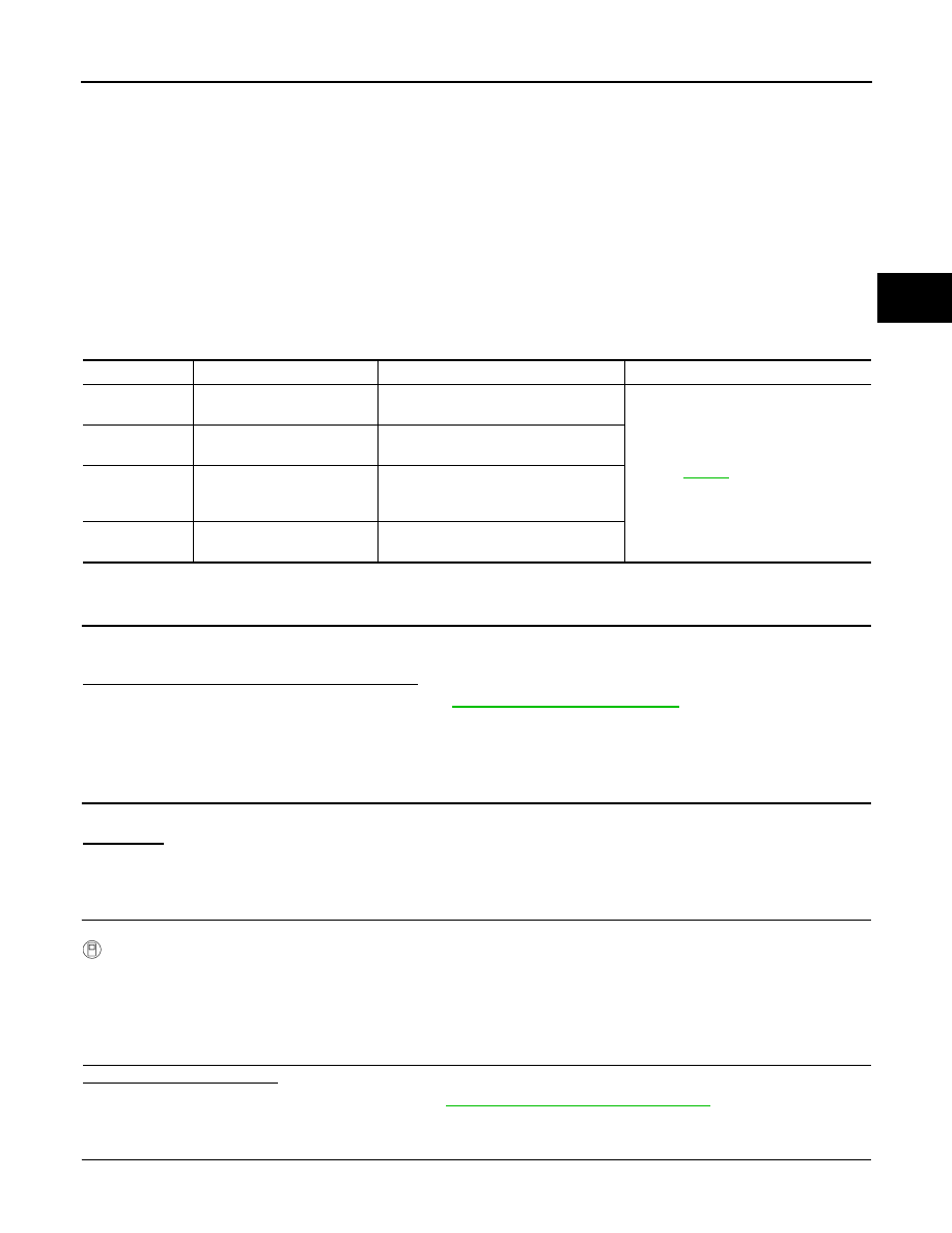
DTC
CONSULT-III
Diagnostic item is detected when...
Reference
[P1802]
CONTROL UNIT 1
Malfunction is detected in the memory
(RAM) system of transfer control unit.
[P1803]
CONTROL UNIT 2
Malfunction is detected in the memory
(ROM) system of transfer control unit.
[P1804]
CONTROL UNIT 3
Malfunction is detected in the memory
(EEPROM) system of transfer control
unit.
[P1809]
CONTROL UNIT 4
AD converter system of transfer control
unit is malfunctioning.

DLN-26
< COMPONENT DIAGNOSIS >
[ATX14B]
P1802 – P1804, P1809 TRANSFER CONTROL UNIT
Without CONSULT-III
1. Perform the self-diagnosis and then erase self-diagnostic results. Refer to
2. Perform the self-diagnosis again.
Do the self-diagnostic results indicate AD converter?
YES
>> Replace transfer control unit. Refer to
DLN-130, "Removal and Installation"
.
NO
>> Inspection End.
Нет комментариевНе стесняйтесь поделиться с нами вашим ценным мнением.
Текст