Infiniti QX56 (JA60). Manual — part 273

4WD SYSTEM
DLN-15
< FUNCTION DIAGNOSIS >
[ATX14B]
C
E
F
G
H
I
J
K
L
M
A
B
DLN
N
O
P
TRANSFER FLUID TEMPERATURE SENSOR
The transfer fluid temperature sensor detects the transfer fluid temperature and sends a signal to the transfer
control unit.
TRANSFER MOTOR
• The transfer motor drives the sub-oil pump to provide proper lubrication and oil pressure control when the
vehicle is at standstill, during low-speed operations or is being driven in reverse.
• The main oil pump is operated by the driving force of the mainshaft. In other words, sufficient oil pressure
buildup does not occur when the vehicle is at standstill or during low-speed operations. While the vehicle is
being driven in reverse, the main oil pump rotates in the reverse direction. Therefore the main oil pump does
not discharge oil pressure. During any of the above vehicle operations, the transfer motor drives the sub-oil
pump to compensate for insufficient oil pressure.
• The transfer motor operates as follows:
- The motor relay turns OFF in the 2WD mode.
- The motor relay operates as described in the table below in modes other than the 2WD mode.
• 4WD shift switch, transmission range switch, Neutral-4LO switch, vehicle speed sensor and throttle position
sensor are used in conjunction with the transfer motor.
Transfer Motor Relay Operation
*: After 2.5 seconds have elapsed.
CLUTCH PRESSURE SOLENOID VALVE
The clutch pressure solenoid valve distributes front and rear torque in AUTO mode.
2-4WD SHIFT SOLENOID VALVE
The 2-4WD shift solenoid valve operates to apply oil pressure to the wet-multiplate clutch, depending on the
drive mode. The driving force is transmitted to the front wheels through the clutch so the vehicle is set in the
4WD mode. Setting the vehicle in the 2WD mode requires no pressure buildup. In other words, pressure force
applied to the wet-multiplate clutch becomes zero.
TRANSFER CONTROL DEVICE
Integrates actuator motor and actuator position switch.
4WD shift switch
A/T selector lever position
Vehicle speed
(VSS)
Accelerator pedal position
Motor relay drive
command
2WD
—
—
—
OFF
4H (LOCK) and 4LO
N position
0
—
ON
P position
0
0 - 0.07/8
OFF*
0.07/8 - 1/8
HOLD
1/8 - MAX
ON
Other than R position
0 < VSS
≤ 50 km/h (31 MPH)
—
ON
50 km/h (31 MPH) < VSS < 55
km/h (34 MPH)
HOLD
55 km/h (34 MPH)
≤ VSS
OFF
R position
—
—
ON
R position
—
—
ON
AUTO
P or N position
0
0 - 0.07/8
OFF*
0.07/8 - 1/8
HOLD
1/8 - MAX
ON
0 < VSS
≤ 50 km/h (31 MPH)
—
ON
50 km/h (31 MPH) < VSS < 55
km/h (34 MPH)
HOLD
55 km/h (34 MPH)
≤ VSS
OFF
Other than R, P and N posi-
tion
0 < VSS
≤ 50 km/h (31 MPH)
—
ON
50 km/h (31 MPH) < VSS < 55
km/h (34 MPH)
HOLD
55 km/h (34 MPH)
≤ VSS
OFF
DLN-16
< FUNCTION DIAGNOSIS >
[ATX14B]
4WD SYSTEM
Actuator Motor
Moves shift rods when signaled by transfer control unit.
Actuator Position Switch
Detects actuator motor position and then sends signal to transfer control unit.
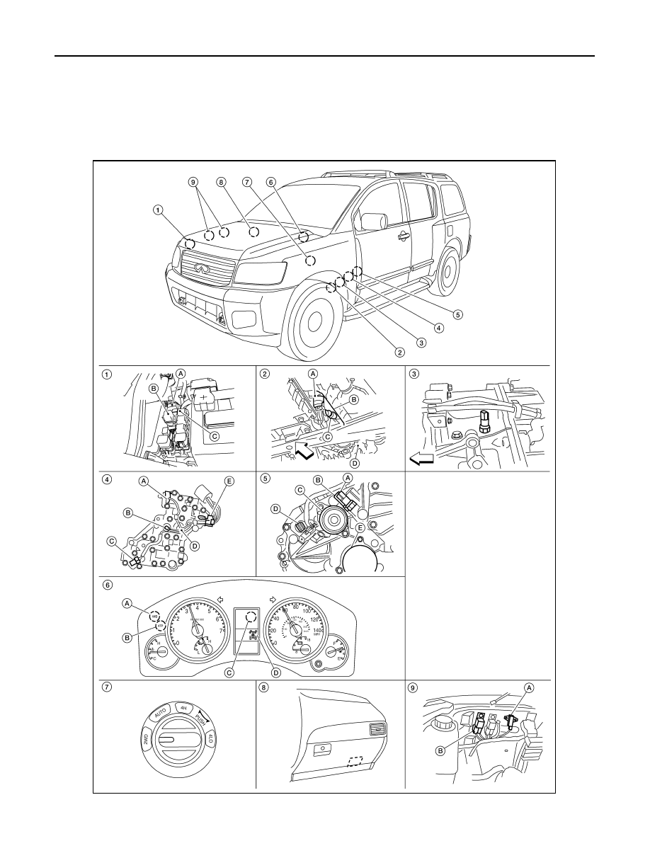
Component Parts Location
INFOID:0000000005148772
AWDIA0549ZZ
4WD SYSTEM
DLN-17
< FUNCTION DIAGNOSIS >
[ATX14B]
C
E
F
G
H
I
J
K
L
M
A
B
DLN
N
O
P
CAN Communication
INFOID:0000000005148773
LAN-14, "Trouble Diagnosis Flow Chart"
1.
A: Transfer shut off relay E69
B: Transfer shift low relay E47
C: Transfer shift high relay E46
2.
A: Actuator
B: Transfer control device F58
C: Actuator lever
D: Transfer case
3.
Wait detection switch F59
(View with transfer case removed)
4.
A: Clutch pressure switch
B: Line pressure switch
C: Transfer fluid temperature sensor
D: 2-4WD shift solenoid valve
E: Clutch pressure solenoid valve
(View with control valve removed
from transfer case)
5.
A: Neutral 4LO switch F60
B: ATP switch F55
C: Transfer motor F57
D: Transfer terminal cord assembly F56
E: Oil filter
6.
Combination meter M23, M24
A: 4WD warning lamp
B: ATP warning lamp
C: 4LO indicator lamp (located in in-
formation display)
D: 4WD shift indicator lamp
7.
4WD shift switch M141
8.
Transfer control unit E142, E143
9.
A: Transfer dropping resistor E135
B: Transfer motor relay E153, E154
(View with battery removed)

DLN-18
< FUNCTION DIAGNOSIS >
[ATX14B]
DIAGNOSIS SYSTEM (TRANSFER CONTROL UNIT)
DIAGNOSIS SYSTEM (TRANSFER CONTROL UNIT)
CONSULT-III Function (ALL MODE AWD/4WD)
INFOID:0000000005148774
FUNCTION
CONSULT-III can display each diagnostic item using the diagnostic test modes shown following.
SELF DIAGNOSTIC RESULT MODE
Operation Procedure
1. Connect CONSULT-III.
2. With engine at idle, touch SELF-DIAG RESULTS.
Display shows malfunction experienced since the last erasing operation.
NOTE:
The details for TIME are as follows:
• 0: Error currently detected with transfer control unit.
• Except for 0: Error detected in the past and memorized with transfer control unit.
Detects frequency of driving after DTC occurs (frequency of turning ignition switch ON/OFF).
How to Erase Self-diagnostic Results
1. Perform applicable inspection of malfunctioning item and then repair or replace.
2. Start engine and select SELF-DIAG RESULTS mode for ALL MODE AWD/4WD with CONSULT-III.
3. Touch ERASE on CONSULT-III screen to erase DTC memory.
CAUTION:
If memory cannot be erased, perform applicable diagnosis.
SELF-DIAGNOSTIC PROCEDURE (WITHOUT CONSULT-III)
Description
If the engine starts when there is a malfunction in the 4WD system, the 4WD warning lamp turns ON or flickers
in the combination meter. When the system functions properly, the warning lamp turns ON when the ignition
switch is turned to ON, and it turns OFF after engine starts. To locate the cause of a malfunction, start the self-
diagnosis function. The 4WD warning lamp in the combination meter will indicate the malfunction area by
flashing according to the self-diagnostic results. Refer to
Diagnostic Procedure
1. Warn up engine.
2. Move A/T selector lever to P position.
3. Turn 4WD shift switch to 2WD position.
4. Turn ignition switch ON and OFF at least twice, and then turn ignition switch OFF.
5. Turn 4WD shift switch to AUTO position.
6. Turn ignition switch ON. (Do not start engine.)
7. 4WD warning lamp ON.
8. Move A/T selector lever to R position.
9. Turn 4WD shift switch to 2WD, AUTO and 2WD in order.
10. Move A/T selector lever to D position.
11. Turn 4WD shift switch to 4H, AUTO and 4H in order.
Diagnostic Mode
Description
Self Diagnostic Result
Displays transfer control unit self-diagnosis results.
Data Monitor
Displays transfer control unit input/output data in real time.
Work Support
Supports inspections and adjustments. Commands are transmitted to the transfer control
unit for setting the status suitable for required operation, input/output signals are received
from the transfer control unit and received data is displayed.
CAN Diag Support Monitor
The results of transmit/receive diagnosis of CAN communication can be read.
ECU Identification
Transfer control unit part number can be read.
Нет комментариевНе стесняйтесь поделиться с нами вашим ценным мнением.
Текст