Infiniti QX56 (JA60). Manual — part 435
EC-392
< COMPONENT DIAGNOSIS >
[VK56DE]
COOLING FAN
COOLING FAN
Diagnosis Procedure
INFOID:0000000005149469
1.
CHECK POWER SUPPLY CIRCUIT
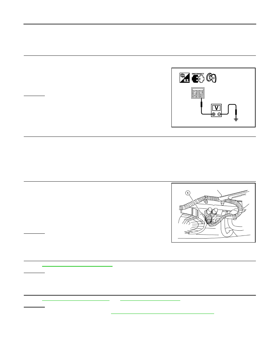
1. Turn ignition switch OFF.
2. Disconnect IPDM E/R harness connector E120.
3. Check voltage between IPDM E/R terminal 22 and ground with
CONSULT-III or tester.
OK or NG
OK
>> GO TO 3.
NG
>> GO TO 2.
2.
DETECT MALFUNCTIONING PART
Check the following.
• 40 A fusible link (letter L)
• 25 A fusible link (letter N)
• Harness for open or short between IPDM E/R and battery
>> Repair open circuit or short to ground or short to power in harness or connectors.
3.
CHECK COOLING FAN MOTOR CIRCUIT FOR OPEN OR SHORT
1. Disconnect cooling fan motor harness connector (1).
2. Check harness continuity between cooling fan motor terminal 2
and IPDM E/R terminal 24, cooling fan motor terminal 1 and
ground.
Refer to wiring diagram.
3. Also check harness for short to ground and short to power.
OK or NG
OK
>> GO TO 4.
NG
>> Repair open circuit or short to ground or short to power
in harness or connectors.
4.
CHECK COOLING FAN MOTOR
EC-392, "Component Inspection"
OK or NG
OK
>> GO TO 5.
NG
>> Replace cooling fan motor.
5.
CHECK INTERMITTENT INCIDENT
Perform
GI-35, "How to Check Terminal"
and
GI-38, "Intermittent Incident"
OK or NG
OK
>> Replace IPDM E/R. Refer to
PCS-35, "Removal and Installation of IPDM E/R"
.
NG
>> Repair or replace harness connectors.
Component Inspection
INFOID:0000000005149470
COOLING FAN MOTOR
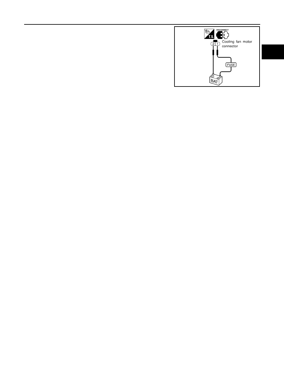
1. Disconnect cooling fan motor harness connector.
Voltage: Battery voltage
PBIB2067E
Continuity should exist.
BBIA0742E
COOLING FAN
EC-393
< COMPONENT DIAGNOSIS >
[VK56DE]
C
D
E
F
G
H
I
J
K
L
M
A
EC
N
P
O
2. Supply cooling fan motor terminals with battery voltage and
check operation.
Cooling fan motor should operate.
If NG, replace cooling fan motor.
SEF888V

EC-394
< COMPONENT DIAGNOSIS >
[VK56DE]
ELECTRICAL LOAD SIGNAL
ELECTRICAL LOAD SIGNAL
Description
INFOID:0000000005149471
The electrical load signal (Headlamp switch signal, rear window defogger switch signal, etc.) is transferred
through the CAN communication line from BCM to ECM via IPDM E/R.
Diagnosis Procedure
INFOID:0000000005149472
1.
CHECK LOAD SIGNAL CIRCUIT OVERALL FUNCTION-I
1. Turn ignition switch ON.
2. Connect CONSULT-III and select “DATA MONITOR” mode.
3. Select “LOAD SIGNAL” and check indication under the following conditions.
OK or NG
OK
>> GO TO 2.
NG
>> GO TO 4.
2.
CHECK LOAD SIGNAL CIRCUIT OVERALL FUNCTION-II
Check “LOAD SIGNAL” indication under the following conditions.
OK or NG
OK
>> GO TO 3.
NG
>> GO TO 5.
3.
CHECK HEATER FAN SIGNAL CIRCUIT OVERALL FUNCTION
Select “HEATER FAN SW” and check indication under the following conditions.
OK or NG
OK
>> INSPECTION END
NG
>> GO TO 6.
4.
CHECK REAR WINDOW DEFOGGER SYSTEM
>> INSPECTION END
5.
CHECK HEADLAMP SYSTEM
>> INSPECTION END
6.
CHECK HEATER FAN CONTROL SYSTEM
.
Condition
Indication
Rear window defogger switch: ON
ON
Rear window defogger switch: OFF
OFF
Condition
Indication
Lighting switch: ON at 2nd position
ON
Lighting switch: OFF
OFF
Condition
Indication
Heater fan control switch: ON
ON
Heater fan control switch: OFF
OFF
ELECTRICAL LOAD SIGNAL
EC-395
< COMPONENT DIAGNOSIS >
[VK56DE]
C
D
E
F
G
H
I
J
K
L
M
A
EC
N
P
O
>> INSPECTION END
Нет комментариевНе стесняйтесь поделиться с нами вашим ценным мнением.
Текст