Infiniti QX56 (JA60). Manual — part 230
DOOR LOCK ACTUATOR
DLK-91
< COMPONENT DIAGNOSIS >
[WITH INTELLIGENT KEY SYSTEM]
C
D
E
F
G
H
I
J
L
M
A
B
DLK
N
O
P
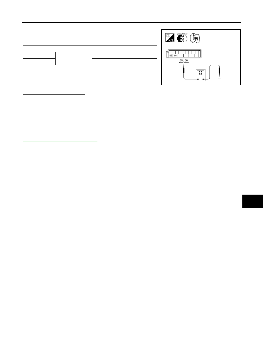
1. Disconnect BCM and rear door lock actuator RH.
2. Check continuity between BCM connector (A) M20 terminals 65,
66 and ground.
Is the inspection result normal?
YES
>> Replace BCM. Refer to
BCS-59, "Removal and Installation"
NO
>> Repair or replace harness or passenger select unlock relay.
BACK DOOR
BACK DOOR : Description
INFOID:0000000005146958
All vehicles equipped with an automatic back door system are not equipped with a back door lock actuator.
Opening and closing the back door is accomplished through the back door control unit assembly. Refer to
DLK-123, "Self-Diagnosis Procedure"
.
Terminals
Continuity
65
Ground
No
66
No
ALKIA0631ZZ
DLK-92
< COMPONENT DIAGNOSIS >
[WITH INTELLIGENT KEY SYSTEM]
GLASS HATCH LOCK ACTUATOR
GLASS HATCH LOCK ACTUATOR
Diagnosis Procedure
INFOID:0000000005146959
Regarding Wiring Diagram information, refer to
DLK-157, "Wiring Diagram — POWER DOOR LOCK SYS-
1.
CHECK GLASS HATCH LOCK ACTUATOR SIGNAL
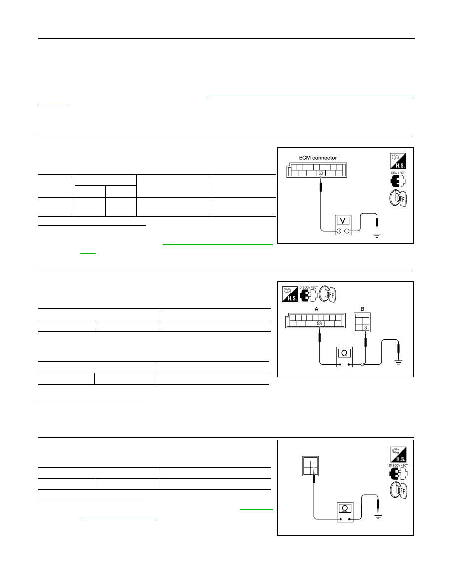
1. Turn ignition switch OFF.
2. Check voltage between BCM connector M19 terminal 53 and
ground.
Is the inspection result normal?
YES
>> GO TO 2.
NO
BCS-59, "Removal and Installa-
.
2.
CHECK GLASS HATCH LOCK ACTUATOR HARNESS
1. Disconnect BCM and glass hatch lock actuator.
2. Check continuity between BCM connector (A) M19 terminal 53
and glass hatch lock actuator connector (B) D711 terminal 3.
3. Check continuity between BCM connector M19 terminals 53 and
ground.
Is the inspection result normal?
YES
>> GO TO 3.
NO
>> Repair or replace harness.
3.
CHECK GLASS HATCH LOCK ACTUATOR GROUND CIRCUIT
Check continuity between glass hatch lock actuator connector D711
terminal 1 and ground.
Is the inspection result normal?
YES
>> Replace glass hatch lock actuator. Refer to
.
NO
>> Repair or replace harness.
Connector
Terminals
Condition
Voltage (V)
(Approx.)
(+)
(-)
M19
53
Ground
Glass hatch switch is
turned to depressed
0
→ Battery voltage
for 300 ms
LIIA1938E
Terminals
Continuity
53
3
Yes
Terminals
Continuity
53
Ground
No
ALKIA1789ZZ
Terminals
Continuity
1
Ground
Yes
ALKIA1790ZZ
PASSENGER SELECT UNLOCK RELAY
DLK-93
< COMPONENT DIAGNOSIS >
[WITH INTELLIGENT KEY SYSTEM]
C
D
E
F
G
H
I
J
L
M
A
B
DLK
N
O
P
PASSENGER SELECT UNLOCK RELAY
Description
INFOID:0000000005146960
Controls the operation of both rear door lock actuators.
Component Function Check
INFOID:0000000005146961
1.
CHECK FUNCTION
1. Ensure "SELECTIVE UNLOCK FUNCTION" in WORK SUPPORT is enabled.
2. Use CONSULT-III to perform Active Test "DOOR LOCK".
3. Touch “ALL LOCK” or “ALL UNLOCK” to check that both rear doors work normally.
Is the inspection result normal?
YES
>> Passenger select unlock relay is OK.
NO
>> Refer to
DLK-93, "Component Function Check"
.
Diagnosis Procedure
INFOID:0000000005146962
Regarding Wiring Diagram information, refer to
DLK-157, "Wiring Diagram — POWER DOOR LOCK SYS-
1.
CHECK PASSENGER SELECT UNLOCK RELAY CIRCUIT
NOTE:
Passenger select unlock relay must remain connected during this step.
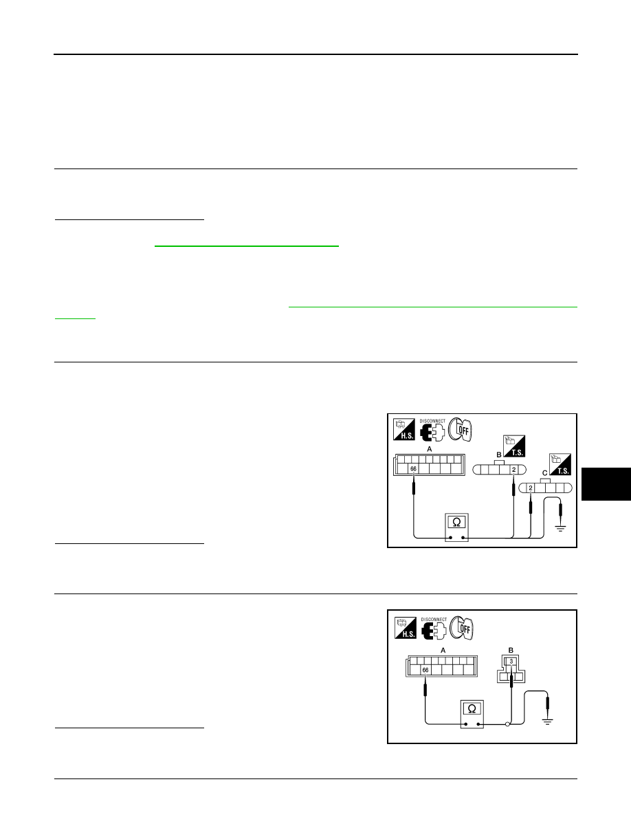
1. Turn ignition switch OFF.
2. Disconnect BCM and inoperative rear door lock actuator.
3. Check continuity between BCM connector (A) M20 terminal 66
and rear door lock actuator LH connector (B) D205 terminal 2 or
rear door lock actuator RH connector (C) D305 Terminal 2.
4. Check continuity between BCM connector M20 terminal 66 and
body ground.
Is the inspection result normal?
YES
>> GO TO 4
NO
>> GO TO 2
2.
CHECK PASSENGER SELECT UNLOCK RELAY INPUT
1. Disconnect passenger select unlock relay.
2. Check continuity between BCM connector (A) M20 terminal 66
and passenger select unlock relay connector (B) M7 terminal 3.
3. Check continuity between BCM connector (A) M20 terminal 66
and body ground.
Is the inspection result normal?
YES
>> GO TO 3
NO
>> Repair or replace harness between BCM and relay.
3.
CHECK PASSENGER SELECT UNLOCK RELAY OUTPUT
66 - 2
: Continuity should exist.
66 - Ground
: Continuity should not exist.
ALKIA1634ZZ
66 - 3
: Continuity should exist.
66 - Ground
: Continuity should not exist.
ALKIA1635ZZ
DLK-94
< COMPONENT DIAGNOSIS >
[WITH INTELLIGENT KEY SYSTEM]
PASSENGER SELECT UNLOCK RELAY
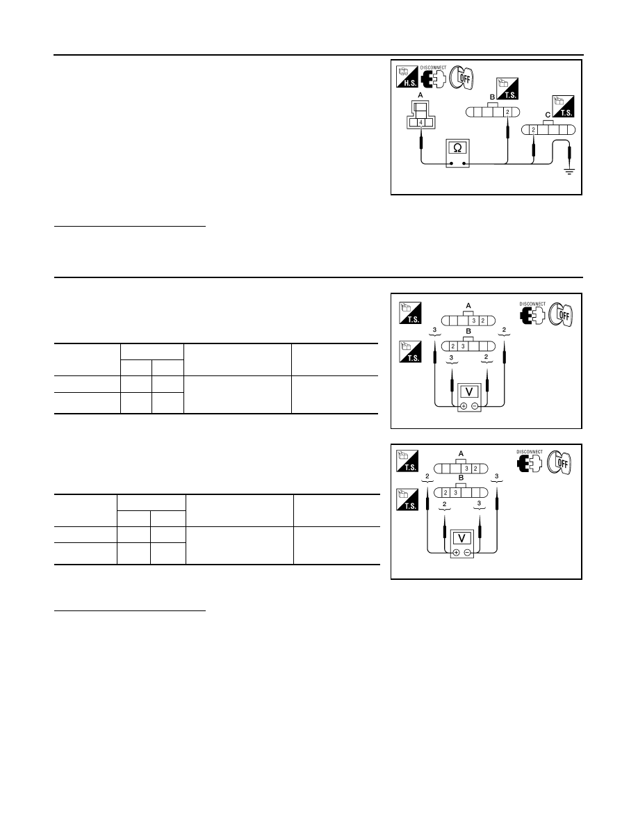
1. Check continuity between passenger select unlock relay con-
nector (A) M7 terminal 4 and rear door lock actuator LH connec-
tor (B) D205 terminal 2 or rear door lock actuator RH connector
(C) D305 terminal 2.
2. Check continuity between passenger select unlock relay con-
nector (A) M7 terminal 4 and ground.
Is the inspection result normal?
YES
>> Replace passenger select unlock relay.
NO
>> Repair or replace harness between relay and actuator.
4.
CHECK REAR DOOR LOCK ACTUATOR ASSEMBLY
1. Reconnect BCM.
2. Check voltage between rear door lock actuator connector LH (A)
D205 terminals 2 and 3 or rear door lock actuator connector RH
(B) D305 terminals 2 and 3.
3. Check voltage between rear door lock actuator connector LH (A)
D205 or rear door lock actuator connector RH (B) D305 termi-
nals 2 and 3.
Is the inspection result normal?
YES
>> Replace rear door lock actuator.
NO
>> Repair or replace harness between actuator and splice.
4 - 2
: Continuity should exist.
4 - Ground
: Continuity should not exist.
ALKIA1636ZZ
Connector
Terminals
Condition
Voltage (V)
(Approx.)
(+)
(-)
A: D205 (LH)
3
2
Main power window and
door lock/unlock switch is
turned to LOCK
0
→ Battery voltage
for 300 msec.
B: D305 (RH)
3
2
ALKIA1637ZZ
Connector
Terminals
Condition
Voltage (V)
(Approx.)
(+)
(-)
A: D205 (LH)
2
3
Main power window and
door lock/unlock switch is
turned to UNLOCK
0
→ Battery voltage
for 300 msec.
B: D305 (RH)
2
3
ALKIA1638ZZ
Нет комментариевНе стесняйтесь поделиться с нами вашим ценным мнением.
Текст