Infiniti QX56 (JA60). Manual — part 309
TRANSFER ASSEMBLY
DLN-159
< DISASSEMBLY AND ASSEMBLY >
[ATX14B]
C
E
F
G
H
I
J
K
L
M
A
B
DLN
N
O
P
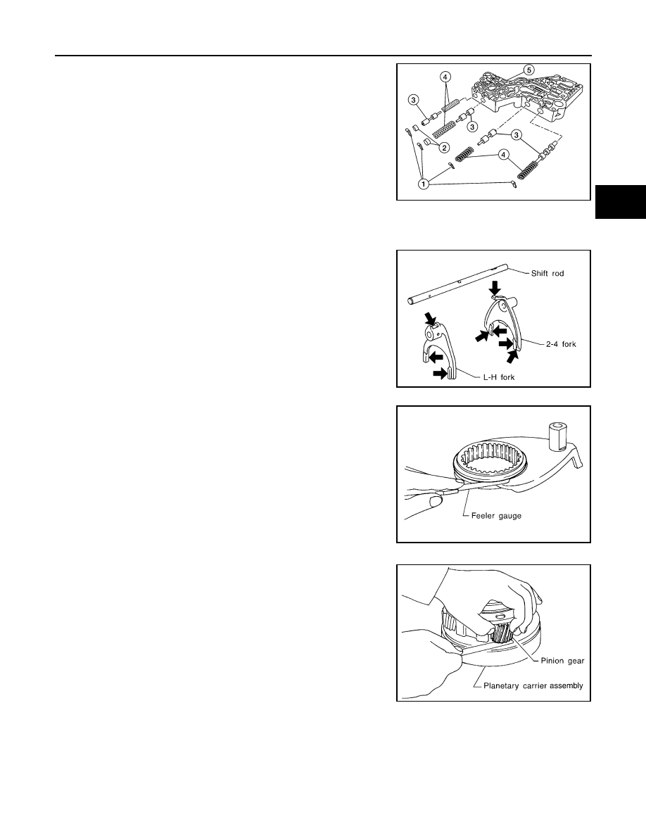
g. Remove each retainer plate (1), plug (2), control valve (3) and
spring (4) from the upper body (5).
INSPECTION AFTER DISASSEMBLY
Shift Rod Components
• Check the working face of the shift rod and fork for wear, partial
wear, bending and other abnormality. If any is found, replace with a
new one.
• Measure the clearance between the shift fork and sleeve. If it is out
of specification, replace it with a new one.
Planetary Carrier
• Measure the end play of each pinion gear. If it is out of specifica-
tion, replace the planetary carrier assembly with a new one.
• Check the working face of each gear and bearing for damage,
burrs, partial wear, dents and other abnormality. If any is found,
replace the planetary carrier assembly with a new one.
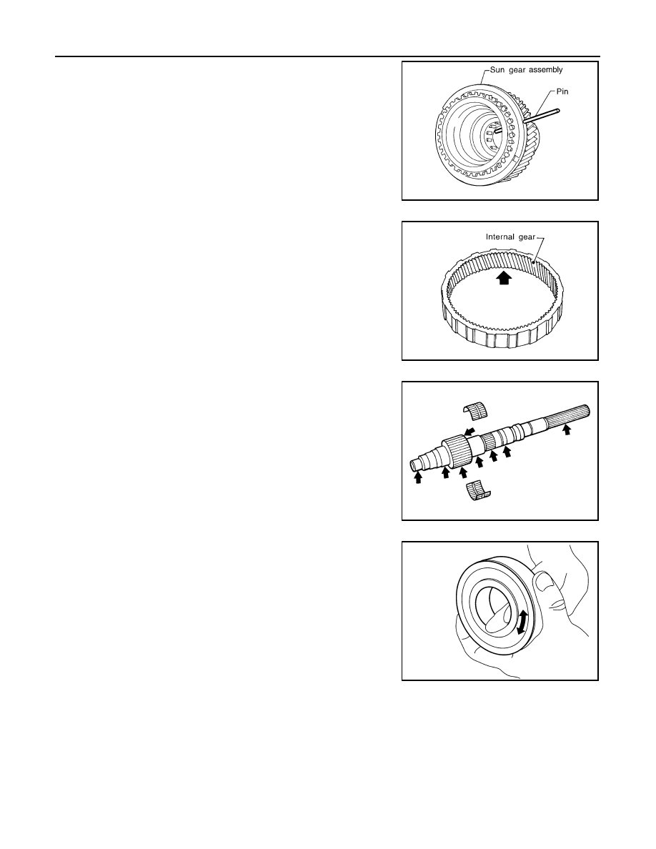
Sun Gear
WDIA0284E
SMT009D
Specification
: Less than 0.36 mm (0.0142 in)
SMT010D
Pinion gear end play
: 0.1 - 0.7 mm (0.004 - 0.028 in)
PDIA0185E
DLN-160
< DISASSEMBLY AND ASSEMBLY >
[ATX14B]
TRANSFER ASSEMBLY
• Check if the oil passage of the sun gear assembly is clogged. For
this, try to pass a 3.6 mm (0.142 in) dia. pin through the oil pas-
sage as shown.
• Check the sliding and contact surface of each gear and bearing for
damage, burrs, partial wear, dents, and other abnormality. If any is
found, replace the sun gear assembly with a new one.
Internal Gear
• Check the internal gear teeth for damage, partial wear, dents and
other abnormality. If any is found, replace the internal gear with a
new one.
Gears and Drive Chain
• Check the gear faces and shaft for wear, cracks, damage, and sei-
zure.
• Check the surfaces which contact the sun gear, clutch drum, clutch
hub, press flange, clutch piston and each bearing for damage,
peel, partial wear, dents, bending, or other abnormal damage. If
any is found, replace with a new one.
Bearing
• Make sure the bearings roll freely and are free from noise, pitting
and cracks.
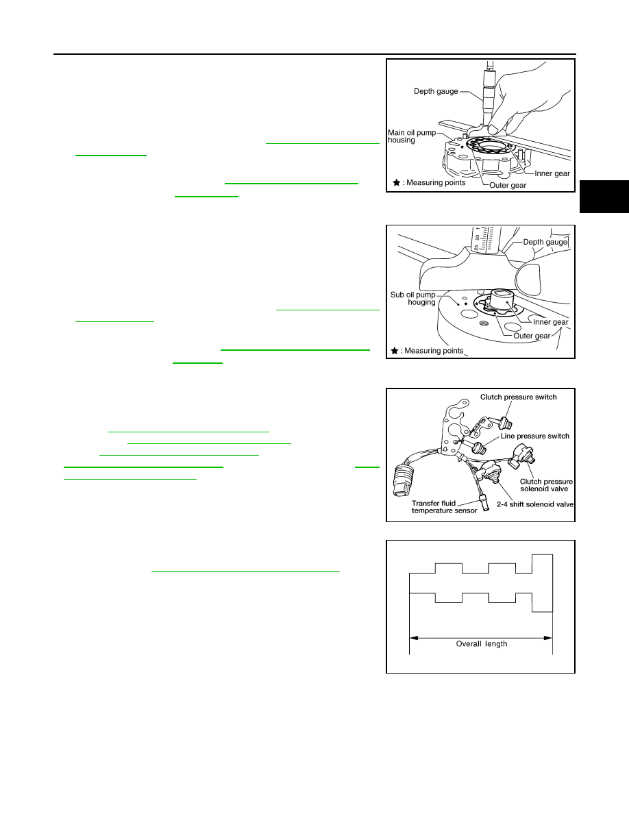
Main Oil Pump
PDIA0186E
SMT008D
SMT944C
SDIA2175E
TRANSFER ASSEMBLY
DLN-161
< DISASSEMBLY AND ASSEMBLY >
[ATX14B]
C
E
F
G
H
I
J
K
L
M
A
B
DLN
N
O
P
1. Check the inner and outer circumference, tooth face, and side-
face of the inner and outer gears for damage or abnormal wear.
2. Measure the side clearance between the main oil pump housing
edge and the inner and outer gears.
3. Make sure the side clearance is within specification. If the mea-
surement is out of specification, replace the inner and outer
gears with new ones as a set. Refer to
.
Sub-oil Pump
1. Check the inner and outer circumference, tooth face, and side-
face of the inner and outer gears for damage or abnormal wear.
2. Measure the side clearance between the sub oil pump housing
edge and the inner and outer gears.
3. Make sure the side clearance is within specification. If the mea-
surement is out of specification, replace the inner and outer
gears with new ones as a set. Refer to
Control Valve
• Check resistance between the terminals of the clutch pressure
solenoid valve, 2-4WD shift solenoid valve, clutch pressure switch,
line pressure switch and the transfer fluid temperature sensor.
Refer to
DLN-57, "Component Inspection"
(clutch pressure sole-
noid valve),
DLN-61, "Component Inspection"
(2-4WD solenoid
valve),
DLN-73, "Component Inspection"
(clutch pressure switch),
DLN-76, "Component Inspection"
(transfer fluid temperature sensor).
• Check the sliding faces of the control valves and plugs for abnor-
mality. If any is found, replace the control valve assembly with a
DLN-142, "Disassembly and Assembly"
CAUTION:
Replace control valve body together with clutch return spring
as a set.
Specification
: Refer to
SDIA2174E
Specification
: Refer to
SDIA2173E
WDIA0199E
SMT947C
DLN-162
< DISASSEMBLY AND ASSEMBLY >
[ATX14B]
TRANSFER ASSEMBLY
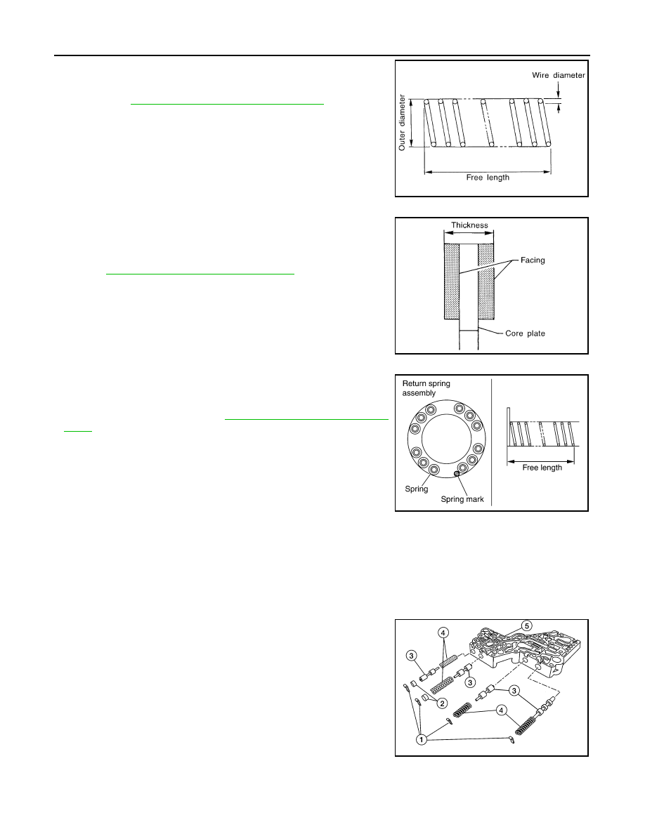
• Check each control valve spring for damage or distortion. Also
check its free length, outer diameter and wire diameter. If any dam-
age or fatigue is found, replace the control valve body with a new
DLN-142, "Disassembly and Assembly"
CAUTION:
Replace control valve body together with clutch return spring
as a set.
Clutch
• Check the drive plate facings and driven plate for damage, cracks
or other abnormality. If any abnormalities are found, replace with a
new one.
• Check the thickness of the drive plate facings and driven plate.
DLN-179, "Inspection and Adjustment"
CAUTION:
• Measure facing thickness at 3 points to take an average.
• Check all drive and driven plates.
• Check return spring for damage or deformation.
• Do not remove spring from plate.
Return Spring
• Check the stamped mark shown. Then, check that the free lengths,
(include thickness of plate) are within specifications. If any abnor-
mality is found, replace with a new return spring assembly of the
same stamped number. Refer to
DLN-179, "Inspection and Adjust-
.
ASSEMBLY
Control Valve Assembly
1. Assemble the control valve assembly with the following procedure.
CAUTION:
• Do not reuse any part that has been dropped or damaged.
• Make sure valve is assembled in the proper direction.
• Do not use a magnet because residual magnetism stays during assembly.
a. Clean the upper body (5), control valves (3) and springs (4) with
cleaning agent, and dry with compressed air.
b. Dip the control valves in ATF, and apply ATF to the valve-mount-
ing area of the upper body.
SMT948C
SMT949C
SDIA2176E
WDIA0284E
Нет комментариевНе стесняйтесь поделиться с нами вашим ценным мнением.
Текст