Infiniti QX56 (JA60). Manual — part 308
TRANSFER ASSEMBLY
DLN-155
< DISASSEMBLY AND ASSEMBLY >
[ATX14B]
C
E
F
G
H
I
J
K
L
M
A
B
DLN
N
O
P
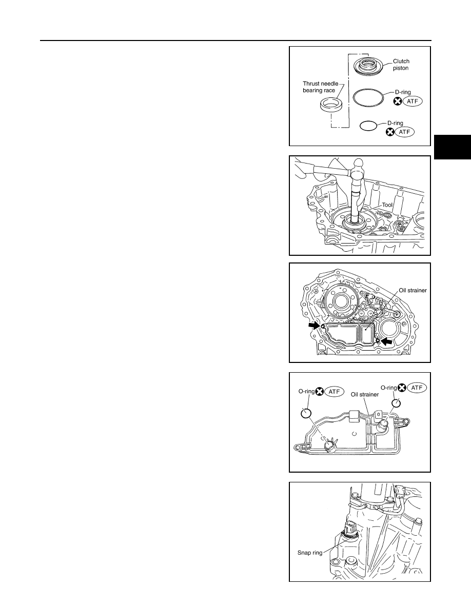
28. Remove the two D-rings from the clutch piston.
29. Remove the mainshaft rear bearing from the center case using
Tool.
30. Remove the two bolts and oil strainer.
31. Remove the two O-rings from the oil strainer.
32. Remove the snap ring. Then push the connector assembly into
the center case to remove the control valve assembly.
SDIA2781E
Tool number
: KV38100300 (J-25523)
SDIA2129E
SDIA2119E
SDIA2782E
SDIA2122E
DLN-156
< DISASSEMBLY AND ASSEMBLY >
[ATX14B]
TRANSFER ASSEMBLY
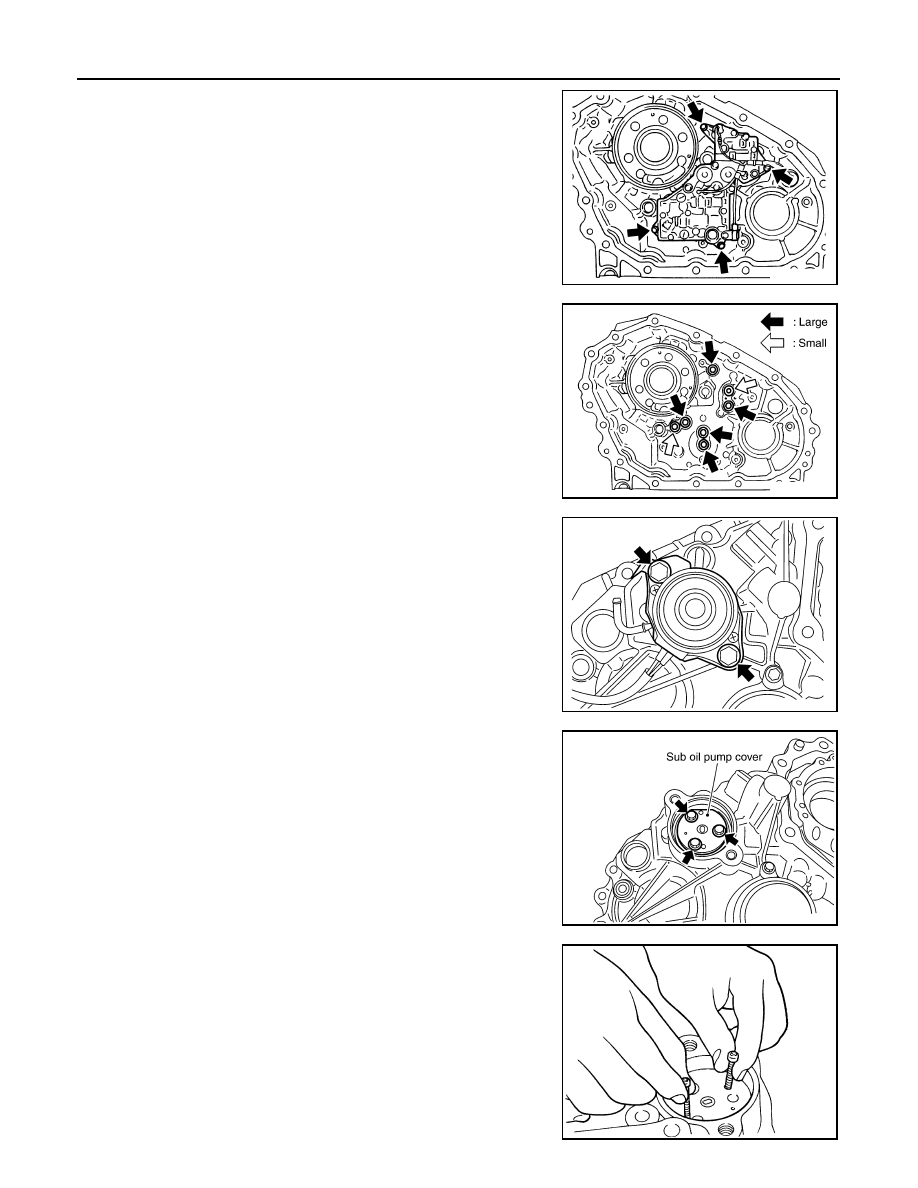
33. Remove the control valve assembly bolts.
34. Remove the control valve assembly.
CAUTION:
• Do not reuse any part that has been dropped or damaged.
• Make sure valve is assembled in the proper direction.
• Do not use a magnet because residual magnetism stays
during disassembly.
35. Remove the lip seals from the center case.
CAUTION:
There are two kinds of lip seals (lip seal of large inner diam-
eter: 5 pieces, lip seal of small inner diameter: 2 pieces).
Confirm the position before disassembly.
36. Remove the transfer motor bolts and motor from the center
case. Then remove the O-ring from the transfer motor.
37. Remove the sub oil pump cover bolts.
38. Thread two bolts (M4 x 0.8) into the holes of sub oil pump cover
as shown, and pull out to remove the sub oil pump assembly.
SDIA2121E
SDIA2123E
SDIA2133E
SDIA2134E
SMT934C
TRANSFER ASSEMBLY
DLN-157
< DISASSEMBLY AND ASSEMBLY >
[ATX14B]
C
E
F
G
H
I
J
K
L
M
A
B
DLN
N
O
P
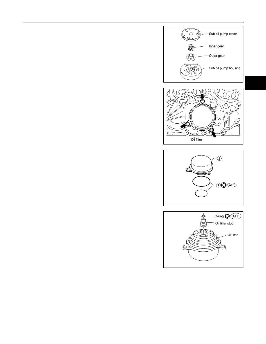
39. Remove the outer gear and inner gear from the sub oil pump
housing.
40. Remove the oil filter bolts and oil filter.
CAUTION:
• Do not damage center case and oil filter.
• Loosen bolts and detach oil filter evenly.
41. Remove the O-rings (1) from the oil filter (2).
42. Remove the oil filter stud from the oil filter.
43. Remove the O-ring from the oil filter stud.
Control Valve Assembly
1. Disassemble the control valve assembly with the following procedure.
CAUTION:
• Do not reuse any part that has been dropped or damaged.
• Make sure valve is assembled in the proper direction.
• Do not use a magnet because residual magnetism stays during disassembly.
SDIA2135E
SDIA2136E
WDIA0285E
SDIA3180E
DLN-158
< DISASSEMBLY AND ASSEMBLY >
[ATX14B]
TRANSFER ASSEMBLY
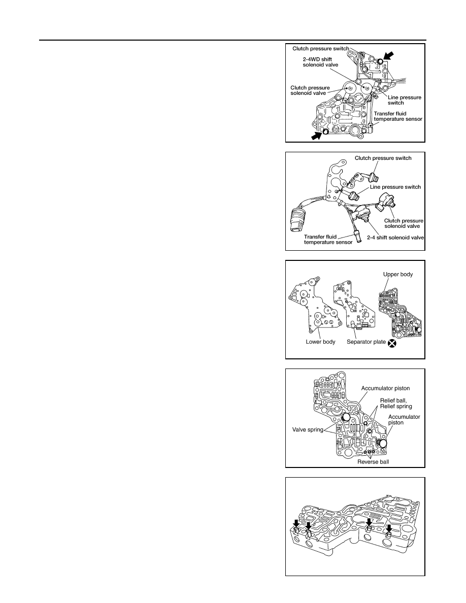
a. Remove all the bolts except for the two shown.
b. Remove the following from the control valve assembly:
• Clutch pressure solenoid valve
• Clutch pressure switch
• 2-4WD shift solenoid valve
• Line pressure switch
• Transfer fluid temperature sensor
c.
Remove the O-rings from each solenoid valve, switch and termi-
nal body.
d. Place the control valve with the lower body facing up. Remove
the two bolts, and then remove the lower body and separator
plate from the upper body.
CAUTION:
Do not drop relief balls. Detach lower body carefully.
e. Make sure the reverse balls, relief balls, relief springs, accumu-
lator pistons and valve springs are securely installed as shown,
and remove them.
f.
Remove the retainer plates.
WDIA0198E
WDIA0199E
WDIA0200E
SDIA2126E
SDIA2127E
Нет комментариевНе стесняйтесь поделиться с нами вашим ценным мнением.
Текст