Infiniti QX56 (JA60). Manual — part 19
PEDAL ADJUSTING SWITCH
ADP-67
< COMPONENT DIAGNOSIS >
C
D
E
F
G
H
I
K
L
M
A
B
ADP
N
O
P
Is the inspection result normal?
YES
>> Replace driver seat control unit. Refer to
ADP-174, "Removal and Installation"
NO
>> Repair or replace the malfunctioning part.
Component Inspection
INFOID:0000000005147505
1.
CHECK PEDAL ADJUSTING SWITCH
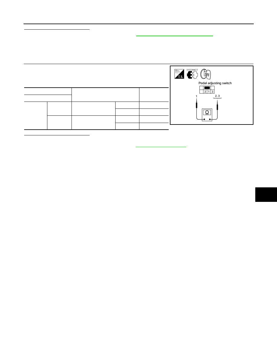
1. Turn ignition switch OFF.
2. Disconnect pedal adjusting switch.
3. Check continuity between pedal adjusting switch terminals.
Is the inspection result normal?
YES
>> Inspection End.
NO
>> Replace pedal adjusting switch. Refer to
Terminal
Condition
Continuity
Pedal adjusting switch
1
2
Pedal adjusting switch
(backward)
Operate
Yes
Release
No
3
Pedal adjusting switch
(forward)
Operate
Yes
Release
No
LIIA1014E
ADP-68
< COMPONENT DIAGNOSIS >
SEAT MEMORY SWITCH
SEAT MEMORY SWITCH
Description
INFOID:0000000005147506
The seat memory switch is installed on the front door LH trim. The operation signal is input to the automatic
drive positioner control unit when the memory switch is operated.
Component Function Check
INFOID:0000000005147507
1.
CHECK FUNCTION
1. Select “MEMORY SW 1”, “MEMORY SW 2”, "SET SW" in “Data monitor” mode with CONSULT-III.
2. Check seat memory switch signal under the following conditions.
Is the indication normal?
YES
>> Inspection End.
NO
>> Perform diagnosis procedure. Refer to
Diagnosis Procedure
INFOID:0000000005147508
Regarding Wiring Diagram information, refer to
1.
CHECK MEMORY SWITCH CIRCUIT
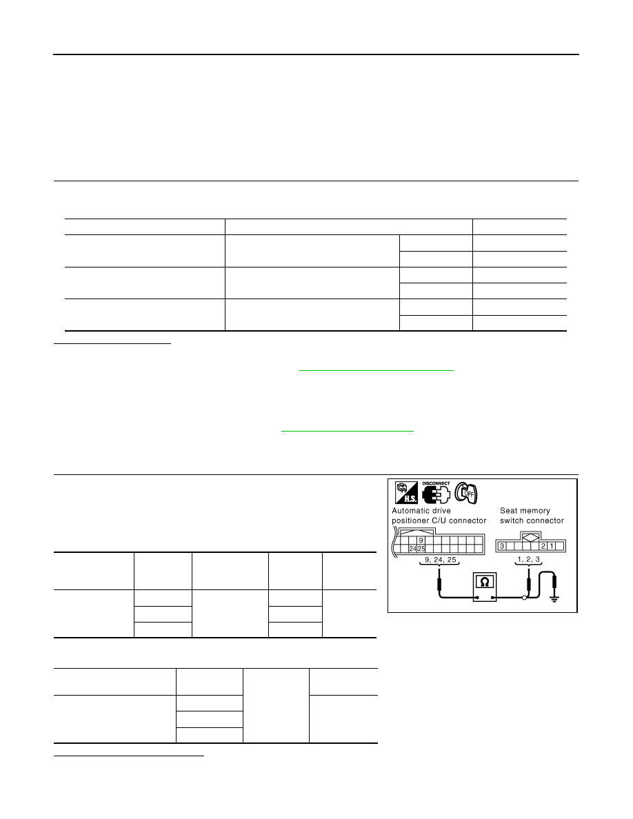
1. Turn ignition switch OFF.
2. Disconnect automatic drive positioner control unit and seat
memory switch.
3. Check continuity between automatic drive positioner control unit
harness connector and seat memory switch harness connector.
4. Check continuity between automatic drive positioner control unit harness connector and ground.
Is the inspection result normal?
YES
>> GO TO 2
NO
>> Repair or replace harness.
Monitor item
Condition
Status
MEMORY SW1
Memory switch 1
Push
ON
Release
OFF
MEMORY SW2
Memory switch 2
Push
ON
Release
OFF
SET SW
Set switch
Push
ON
Release
OFF
Automatic drive
positioner control
unit connector
Terminal
Seat memory
switch connector
Terminal
Continuity
M33
9
D5
1
Yes
24
3
25
2
Automatic drive positioner
control unit connector
Terminal
Ground
Continuity
M33
9
No
24
25
PIIA4576E
SEAT MEMORY SWITCH
ADP-69
< COMPONENT DIAGNOSIS >
C
D
E
F
G
H
I
K
L
M
A
B
ADP
N
O
P
2.
CHECK MEMORY SWITCH GROUND CIRCUIT
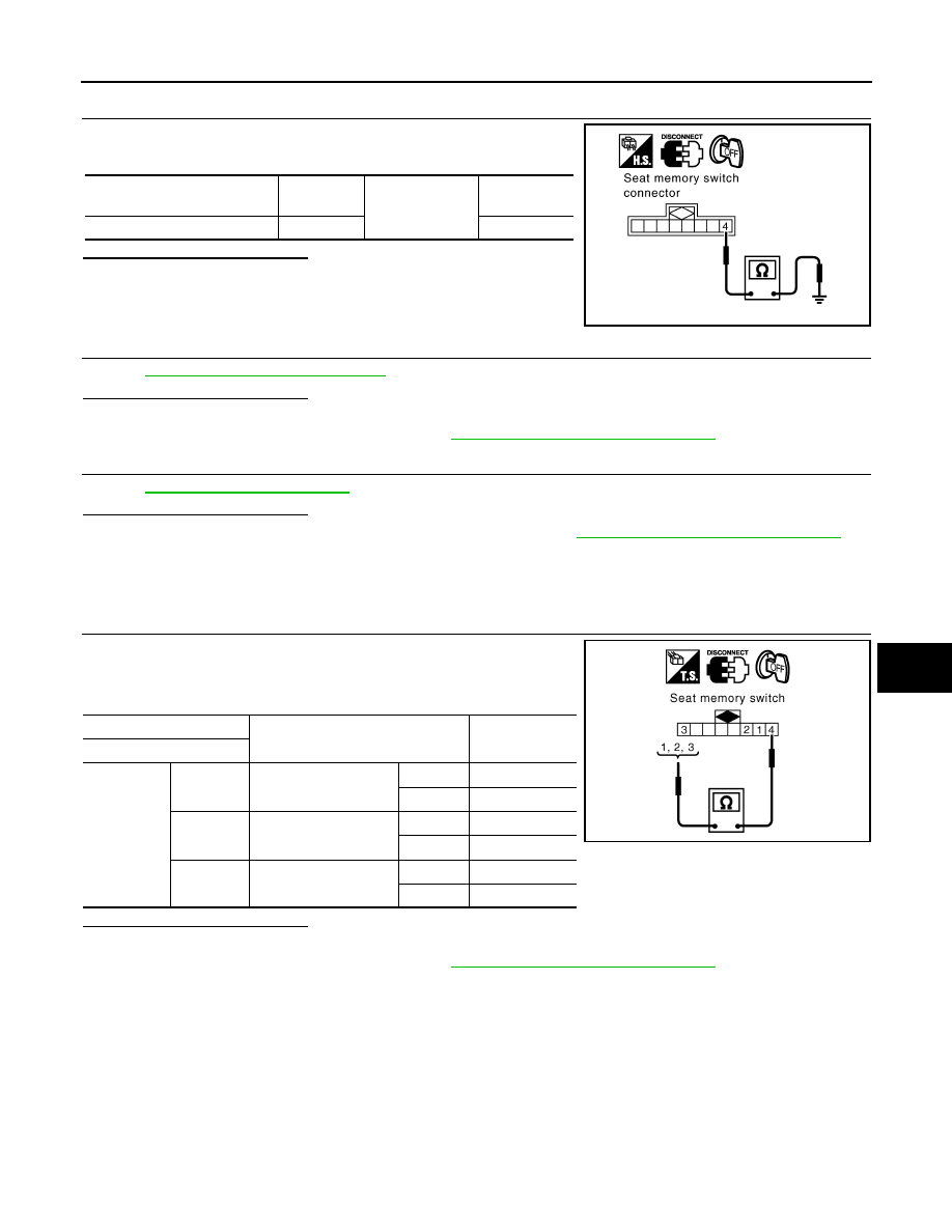
Check continuity between seat memory switch harness connector
and ground.
Is the inspection result normal?
YES
>> GO TO 3
NO
>> Repair or replace harness.
3.
CHECK SEAT MEMORY SWITCH
ADP-69, "Component Inspection"
.
Is the inspection result normal?
YES
>> GO TO 4
NO
>> Replace seat memory switch. Refer to
ADP-176, "Removal and Installation"
.
4.
CHECK INTERMITTENT INCIDENT
GI-38, "Intermittent Incident"
.
Is the inspection result normal?
YES
>> Replace automatic drive positioner control unit. Refer to
ADP-175, "Removal and Installation"
.
NO
>> Repair or replace the malfunctioning part.
Component Inspection
INFOID:0000000005147509
1.
CHECK SEAT MEMORY SWITCH
1. Turn ignition switch OFF.
2. Disconnect seat memory switch.
3. Check continuity between seat memory switch terminals.
Is the inspection result normal?
YES
>> Inspection End.
NO
>> Replace seat memory switch. Refer to
ADP-176, "Removal and Installation"
.
Seat memory switch
connector
Terminal
Ground
Continuity
D5
4
Yes
PIIA4821E
Terminal
Condition
Continuity
Seat memory switch
4
1
Memory switch 1
Push
Yes
Release
No
2
Memory switch 2
Push
Yes
Release
No
3
Set switch
Push
Yes
Release
No
LIIA1020E
ADP-70
< COMPONENT DIAGNOSIS >
DOOR MIRROR REMOTE CONTROL SWITCH
DOOR MIRROR REMOTE CONTROL SWITCH
CHANGEOVER SWITCH
CHANGEOVER SWITCH : Description
INFOID:0000000005147510
Changeover switch is integrated into door mirror remote control switch.
Changeover switch has three positions (L, N and R).
It changes door mirror motor operation by transmitting control signal to automatic drive positioner control unit.
CHANGEOVER SWITCH : Component Function Check
INFOID:0000000005147511
1.
CHECK CHANGEOVER SWITCH FUNCTION
Check the operation on “MIR CHNG SW-R” or “MIR CHNG SW-L” in “DATA MONITOR” mode with CON-
SULT-III.
Refer to
ADP-28, "CONSULT-III Function"
Is the inspection result normal?
YES
>> Changeover switch function is OK.
NO
>> Refer to
ADP-70, "CHANGEOVER SWITCH : Diagnosis Procedure"
.
CHANGEOVER SWITCH : Diagnosis Procedure
INFOID:0000000005147512
Regarding Wirng Diagram information, refer to
.
1.
CHECK CHANGEOVER SWITCH SIGNAL
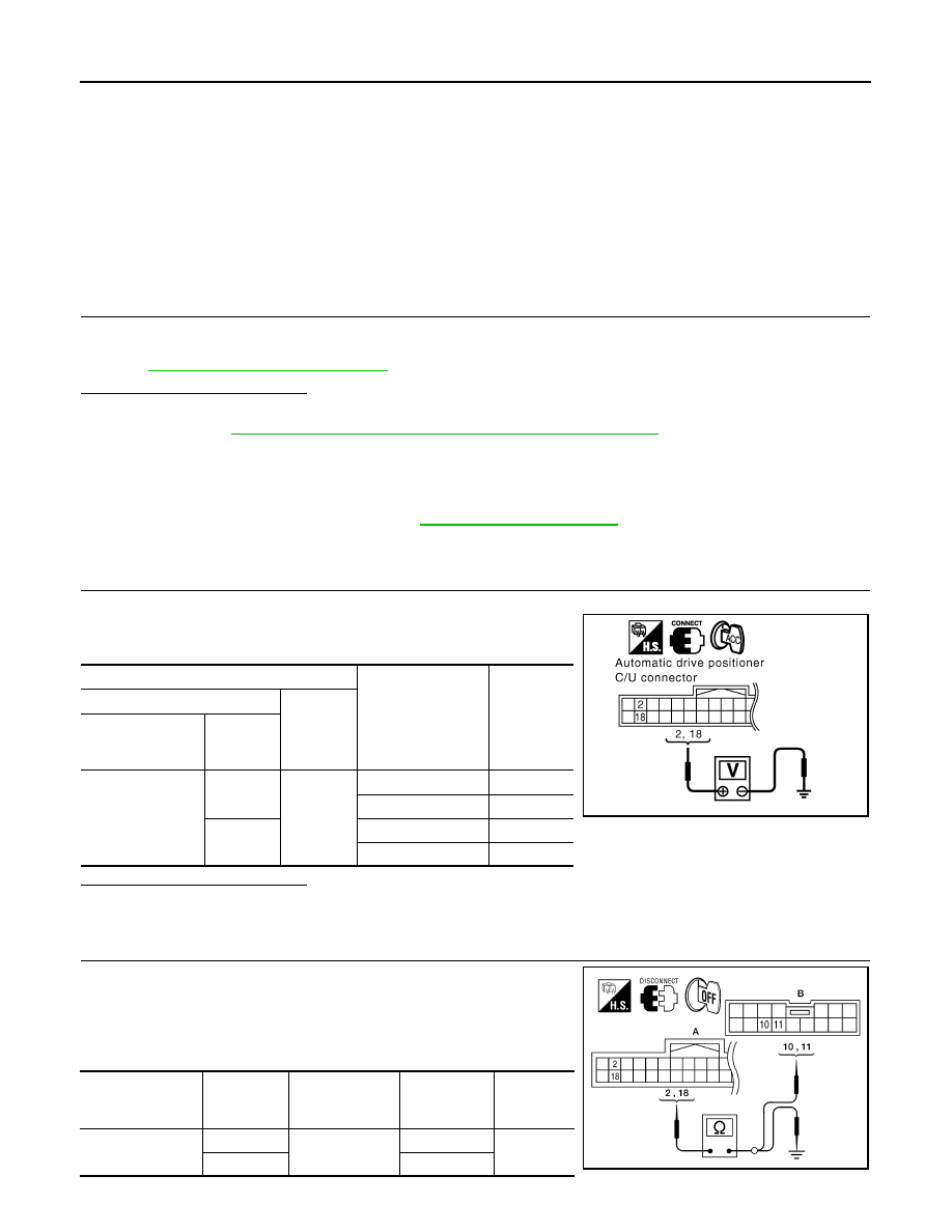
1. Turn ignition switch to ACC.
2. Check voltage between automatic drive positioner control unit
connector and ground.
Is the inspection result normal?
YES
>> GO TO 6
NO
>> GO TO 2
2.
CHECK HARNESS CONTINUITY
1. Turn ignition switch OFF.
2. Disconnect automatic drive positioner control unit and door mir-
ror remote control switch.
3. Check continuity between automatic drive positioner control unit
connector and door mirror remote control switch connector.
Terminals
Change over switch
condition
Voltage (V)
(Approx.)
(+)
(-)
Automatic drive
positioner control
unit connector
Terminal
M33
2
Ground
RIGHT
0
Other than above
5
18
LEFT
0
Other than above
5
PIIA4767E
Automatic drive
positioner control
unit connector
Terminal
Door mirror re-
mote control
switch connector
Terminal
Continuity
M33 (A)
2
D10 (B)
11
Yes
18
10
ALJIA0201ZZ
Нет комментариевНе стесняйтесь поделиться с нами вашим ценным мнением.
Текст