Infiniti QX56 (JA60). Manual — part 18
TILT SWITCH
ADP-63
< COMPONENT DIAGNOSIS >
C
D
E
F
G
H
I
K
L
M
A
B
ADP
N
O
P
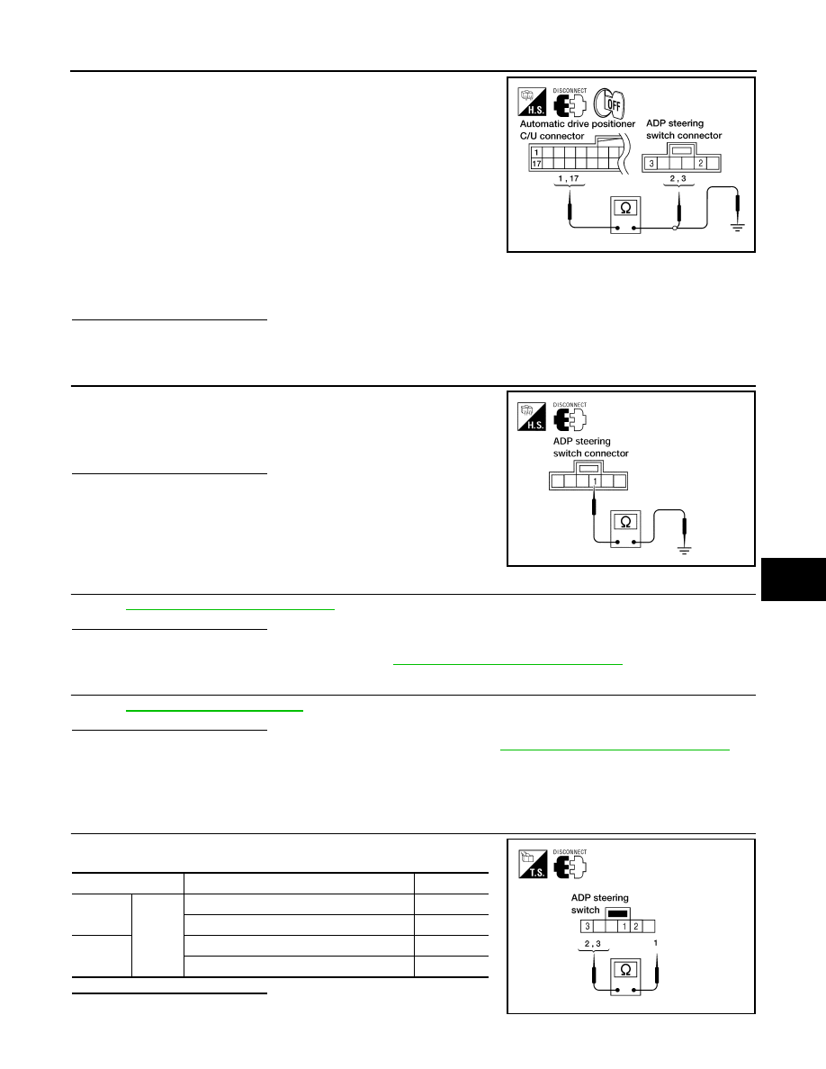
1. Disconnect automatic drive positioner control unit and ADP
steering switch.
2. Check continuity between automatic drive positioner control unit
connector M33 terminals 1, 17 and ADP steering switch connec-
tor M16 terminals 2, 3.
3. Check continuity between automatic drive positioner control unit
connector M33 terminals 1, 17 and ground.
Is the inspection result normal?
YES
>> GO TO 3
NO
>> Repair or replace harness.
3.
CHECK ADP STEERING SWITCH GROUND CIRCUIT
Check continuity between ADP steering switch connector M16 termi-
nal 1 and ground.
Is the inspection result normal?
YES
>> Check the condition of the harness and connector.
NO
>> Replace or replace harness.
4.
CHECK TILT SWITCH
ADP-63, "Component Inspection"
.
Is the inspection result normal?
YES
>> GO TO 5
NO
>> Replace ADP steering switch. Refer to
ADP-179, "Removal and Installation"
5.
CHECK INTERMITTENT INCIDENT
GI-38, "Intermittent Incident"
.
Is the inspection result normal?
YES
>> Replace automatic drive positioner control unit. Refer to
ADP-175, "Removal and Installation"
.
NO
>> Repair or replace the malfunctioning part.
Component Inspection
INFOID:0000000005147501
1.
CHECK ADP STEERING WHEEL TILT SWITCH
Check continuity between ADP steering switch terminals as follows.
Is the inspection result normal?
YES
>> Inspection End.
1 - 2
: Continuity should exist.
17 - 3
: Continuity should exist.
1 - Ground
: Continuity should not exist.
17 - Ground
: Continuity should not exist.
LIIA1434E
1 - Ground
: Continuity should exist.
LIIA0490E
Terminals
Condition
Continuity
2
1
ADP steering switch ON (UP operation)
Yes
Other than above
No
3
ADP steering switch ON (DOWN operation)
Yes
Other than above
No
LIIA1435E
ADP-64
< COMPONENT DIAGNOSIS >
TILT SWITCH
NO
>> Replace ADP steering switch. Refer to
PEDAL ADJUSTING SWITCH
ADP-65
< COMPONENT DIAGNOSIS >
C
D
E
F
G
H
I
K
L
M
A
B
ADP
N
O
P
PEDAL ADJUSTING SWITCH
Description
INFOID:0000000005147502
Pedal adjusting switch is on the instrument panel. The operation signal is input to the driver seat control unit
when the pedal adjusting switch is operated. The pedal adjusting switch signal is sent to the automatic drive
positioner control unit via UART communication.
Component Function Check
INFOID:0000000005147503
1.
CHECK FUNCTION
1. Select “PEDAL SW-FR”, “PEDAL SW-RR” in “Data monitor” mode with CONSULT-III.
2. Check pedal adjusting switch signal under the following conditions.
Is the indication normal?
YES
>> Inspection End.
NO
>> Perform diagnosis procedure. Refer to
Diagnosis Procedure
INFOID:0000000005147504
Regarding Wiring Diagram information, refer to
1.
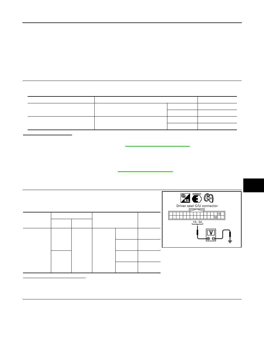
CHECK PEDAL ADJUSTING SWITCH SIGNAL
1. Turn ignition switch OFF.
2. Check voltage between driver seat control unit harness connec-
tor and ground.
Is the inspection result normal?
YES
>> GO TO 5
NO
>> GO TO 2
2.
CHECK PEDAL ADJUSTING SWITCH CIRCUIT
Monitor item
Condition
Status
PEDAL SW-FR
Pedal adjusting switch (forward)
Operate
ON
Release
OFF
PEDAL SW-RR
Pedal adjusting switch (backward)
Operate
ON
Release
OFF
Driver seat
control unit
connector
Terminals
Condition
Voltage (V)
(Approx.)
(+)
(–)
B202
15
Ground
Pedal ad-
justing
switch
Operate
(backward)
0
Release
Battery
voltage
30
Operate
(forward)
0
Release
Battery
voltage
PIIA4591E
ADP-66
< COMPONENT DIAGNOSIS >
PEDAL ADJUSTING SWITCH
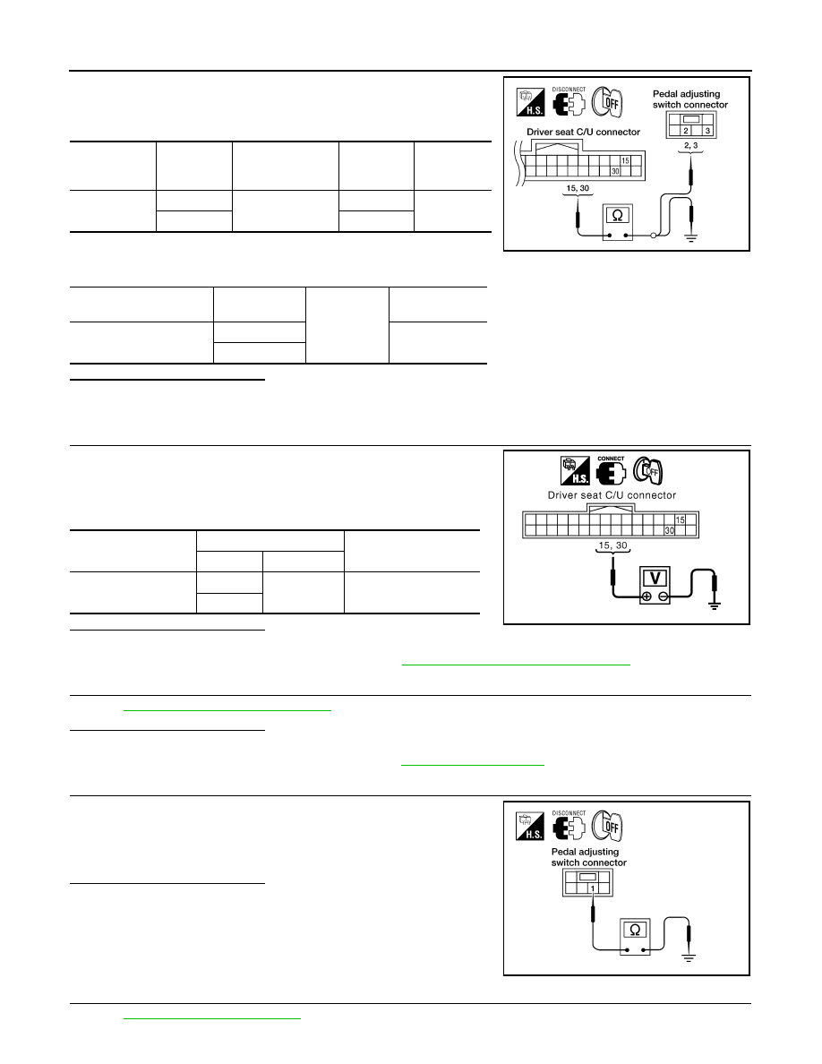
1. Disconnect driver seat control unit and pedal adjusting switch.
2. Check continuity between driver seat control unit harness con-
nector and pedal adjusting switch harness connector.
3. Check continuity between driver seat control unit harness con-
nector and ground.
Is the inspection result normal?
YES
>> GO TO 3
NO
>> Repair or replace harness.
3.
CHECK DRIVER SEAT CONTROL UNIT OUTPUT
1. Connect the driver seat control unit.
2. Turn ignition switch OFF.
3. Check voltage between driver seat control unit harness connec-
tor and ground.
Is the inspection result normal?
YES
>> GO TO 4
NO
>> Replace driver seat control unit. Refer to
ADP-174, "Removal and Installation"
4.
CHECK PEDAL ADJUSTING SWITCH
ADP-67, "Component Inspection"
.
Is the inspection result normal?
YES
>> GO TO 5
NO
>> Replace pedal adjusting switch. Refer to
5.
CHECK PEDAL ADJUSTING SWITCH GROUND CIRCUIT
Check continuity between pedal adjusting switch connector M96 ter-
minal 1 and ground.
Is the inspection result normal?
YES
>> GO TO 6
NO
>> Repair or replace harness.
6.
CHECK INTERMITTENT INCIDENT
GI-38, "Intermittent Incident"
Driver seat
control unit
connector
Terminal
Pedal adjusting
switch connector
Terminal
Continuity
B202
15
M96
2
Yes
30
3
Driver seat control unit
connector
Terminal
Ground
Continuity
B202
15
No
30
LIIA0726E
Driver seat control unit
connector
Terminals
Voltage (V)
(Approx.)
(+)
(–)
B202
15
Ground
Battery voltage
30
PIIA4591E
1 - Ground
: Continuity should exist.
LIIA1015E
Нет комментариевНе стесняйтесь поделиться с нами вашим ценным мнением.
Текст