Infiniti QX56 (JA60). Manual — part 141
C1185 ICC UNIT
BRC-77
< COMPONENT DIAGNOSIS >
[VDC/TCS/ABS]
C
D
E
G
H
I
J
K
L
M
A
B
BRC
N
O
P
C1185 ICC UNIT
Description
INFOID:0000000005148057
When the force applied to brake pedal exceeds a certain level, the brake assist is activated and generates a
greater braking force than that of a conventional brake booster, even with light pedal force.
When the ICC preview function identifies the need to apply the sudden brake by sensing the vehicle ahead in
the same lane and the distance and relative speed from it, it applies the brake pre-pressure before driver
depresses the brake pedal and improves brake response by reducing its free play.
DTC Logic
INFOID:0000000005148058
DTC DETECTION LOGIC
DTC CONFIRMATION PROCEDURE
1.
CHECK SELF-DIAGNOSIS RESULTS
Check the self-diagnosis results.
Is above displayed on the self-diagnosis display?
YES
>> Proceed to diagnosis procedure. Refer to
.
NO
>> Inspection End
Diagnosis Procedure
INFOID:0000000005148059
Regarding Wiring Diagram information, refer to
BRC-92, "Wiring Diagram - BRAKE CONTROL SYSTEM -"
1.
SELF-DIAGNOSIS RESULT CHECK
Perform self-diagnosis of ICC unit.
Are self-diagnosis result items displayed?
YES
>> After checking and repairing the applicable item, perform ICC unit self-diagnosis again.
NO
>> GO TO 2
2.
CONNECTOR INSPECTION
Disconnect the ABS actuator and electric unit (control unit) connector and the ICC unit connector and check
the terminals for deformation, disconnection, looseness or damage.
Is the inspection result normal?
YES
>> GO TO 3
NO
>> Repair or replace as necessary.
3.
ICC UNIT CIRCUIT INSPECTION
DTC
Display item
Malfunction detected condition
Possible cause
C1185
ABS ACC CU INTERNAL NG ICC control unit internal malfunction.
• Harness or connector
• ICC unit
• ABS actuator and electric unit
(control unit)
Self-diagnosis results
ABS ACC CU INTERNAL NG

BRC-78
< COMPONENT DIAGNOSIS >
[VDC/TCS/ABS]
C1185 ICC UNIT
1. Measure the continuity between ABS actuator and electric unit
(control unit) connector E125 terminal 7 and ICC unit connector
B13 terminal 10.
2. Measure the continuity between ABS actuator and electric unit
(control unit) connector E125 terminal 7 and body ground.
Is the inspection result normal?
YES
>> Replace ABS actuator and electric unit (control unit). Refer to
BRC-116, "Removal and Installa-
.
NO
>> Repair or replace harness or connector.
Special Repair Requirement
INFOID:0000000005194923
1.
ADJUSTMENT OF STEERING ANGLE SENSOR NEUTRAL POSITION
Always perform neutral position adjustment for the steering angle sensor when replacing the ABS actuator
and electric unit (control unit). Refer to
BRC-8, "ADJUSTMENT OF STEERING ANGLE SENSOR NEUTRAL
.
>> GO TO 2
2.
CALIBRATION OF DECEL G SENSOR
Always perform calibration of decel G sensor when replacing the ABS actuator and electric unit (control unit).
BRC-9, "CALIBRATION OF DECEL G SENSOR : Description"
>> END
ABS actuator and electric unit
(control unit)
ICC unit
Continuity
Connector
Terminal
Connector
Terminal
E125 (A)
7
B13 (B)
10
Yes
ABS actuator and electric unit (control
unit)
—
Continuity
Connector
Terminal
E125 (A)
7
Ground
No
AWFIA0067ZZ
U1000 CAN COMM CIRCUIT
BRC-79
< COMPONENT DIAGNOSIS >
[VDC/TCS/ABS]
C
D
E
G
H
I
J
K
L
M
A
B
BRC
N
O
P
U1000 CAN COMM CIRCUIT
Description
INFOID:0000000005148061
CAN (Controller Area Network) is a serial communication line for real time application. It is an on-vehicle mul-
tiplex communication line with high data communication speed and excellent error detection ability. Many elec-
tronic control units are equipped onto a vehicle, and each control unit shares information and links with other
control units during operation (not independent). In CAN communication, control units are connected with 2
communication lines (CAN H line, CAN L line) allowing a high rate of information transmission with less wiring.
Each control unit transmits/receives data but selectively reads required data only.
DTC Logic
INFOID:0000000005148062
DTC DETECTION LOGIC
Diagnosis Procedure
INFOID:0000000005148063
1.
CHECK CONNECTOR
1. Turn ignition switch OFF, disconnect the ABS actuator and electric unit (control unit) connector, and check
the terminals for deformation, disconnection, looseness, and so on. If there is a malfunction, repair or
replace the terminal.
2. Reconnect connector and perform self-diagnosis. Refer to
BRC-23, "CONSULT-III Function (ABS)"
.
Is “CAN COMM CIRCUIT” displayed in self-diagnosis display items?
YES
>> Print out the self-diagnostic results, and refer to
LAN-14, "Trouble Diagnosis Flow Chart"
NO
>> Connector terminal is loose, damaged, open, or shorted.
DTC
Display item
Malfunction detected condition
Possible cause
U1000
CAN COMM CIRCUIT
When ABS actuator and electric unit (control unit) is not
transmitting or receiving CAN communication signal for 2
seconds or more.
• CAN communication line
• ABS actuator and electric unit
(control unit)
BRC-80
< COMPONENT DIAGNOSIS >
[VDC/TCS/ABS]
VDC OFF SWITCH
VDC OFF SWITCH
Description
INFOID:0000000005148065
VDC OFF switch can deactivate (turn OFF) the VDC/TCS function by pressing the VDC OFF switch.
Component Function Check
INFOID:0000000005148066
1.
CHECK VDC OFF SWITCH OPERATION
Turn ON/OFF the VDC OFF switch and check that the VDC OFF indicator lamp in the combination meter turns
ON/OFF correctly.
Is the inspection result normal?
YES
>> Inspection End
NO
>> Go to diagnosis procedure. Refer to
Diagnosis Procedure
INFOID:0000000005148067
Regarding Wiring Diagram information, refer to
BRC-92, "Wiring Diagram - BRAKE CONTROL SYSTEM -"
1.
CHECK VDC OFF SWITCH
Perform the VDC OFF switch component inspection. Refer to
BRC-81, "Component Inspection"
.
Is the inspection result normal?
YES
>> GO TO 2
NO
>> Replace VDC OFF switch.
2.
CHECK VDC OFF SWITCH HARNESS
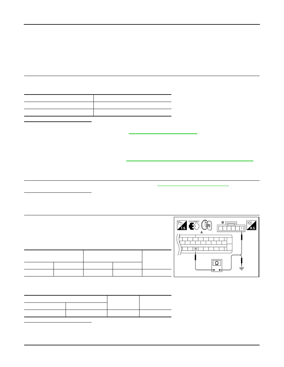
1. Disconnect ABS actuator and electric unit (control unit) connec-
tor.
2. Check continuity between ABS actuator and electric unit (control
unit) connector E125 (A) terminal 38 and VDC OFF switch con-
nector M253 (B) terminal 1.
3. Check continuity between ABS actuator and electric unit (control
unit) connector E125 (A) terminal 38 and ground.
Is the inspection result normal?
YES
>> GO TO 3
NO
>> Repair or replace harness.
3.
CHECK VDC OFF SWITCH GROUND
Condition
VDC OFF indicator lamp illumination status
VDC OFF switch: ON
ON
VDC OFF switch: OFF
OFF
ABS actuator and electric unit
(control unit)
VDC OFF switch
Continuity
Connector
Terminal
Connector
Terminal
E125 (A)
38
M253 (B)
1
Yes
ABS actuator and electric unit (control unit)
—
Continuity
Connector
Terminal
E125 (A)
38
Ground
No
AWFIA0430ZZ
Нет комментариевНе стесняйтесь поделиться с нами вашим ценным мнением.
Текст