Infiniti QX56 (JA60). Manual — part 140
C1178, C1181, C1184, C1189 ABS ACTIVE BOOSTER
BRC-73
< COMPONENT DIAGNOSIS >
[VDC/TCS/ABS]
C
D
E
G
H
I
J
K
L
M
A
B
BRC
N
O
P
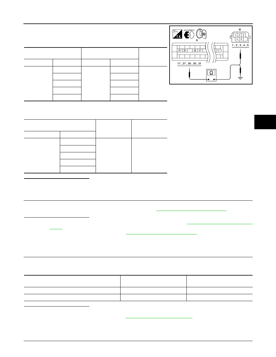
1. Measure the continuity between ABS actuator and electric unit
(control unit) connector E125 (A) and active booster connector
E49 (B).
2. Measure the continuity between ABS actuator and electric unit (control unit) connector E125 (A) and body
ground.
Is the inspection result normal?
YES
>> GO TO 3
NO
>> Repair or replace harness or connector.
3.
ACTIVE BOOSTER INSPECTION
1. Reconnect the active booster and ABS actuator and electric unit (control unit) connectors.
2. Perform the active booster component inspection. Refer to
BRC-73, "Component Inspection"
Is the inspection result normal?
YES
>> Replace the ABS actuator and electric unit (control unit). Refer to
.
NO
>> Replace the active booster. Refer to
BR-26, "Removal and Installation"
.
Component Inspection
INFOID:0000000005148050
1.
CHECK DATA MONITOR
Use “DATA MONITOR” to check if the status of “RELEASE SWITCH NO” and “RELEASE SWITCH NC” is nor-
mal.
Is the inspection result normal?
YES
>> Inspection End
NO
>> Go to diagnosis procedure. Refer to
Special Repair Requirement
INFOID:0000000005194921
1.
ADJUSTMENT OF STEERING ANGLE SENSOR NEUTRAL POSITION
ABS actuator and electric unit
(control unit)
Active booster
Continuity
Connector
Terminal
Connector
Terminal
E125 (A)
17
E49 (B)
3
Yes
27
1
28
5
30
2
31
4
ABS actuator and electric unit (control
unit)
—
Continuity
Connector
Terminal
E125 (A)
17
Ground
No
27
28
30
31
AWFIA0028ZZ
Condition
RELEASE SWITCH NO
(DATA MONITOR)
RELEASE SWITCH NC
(DATA MONITOR)
When brake pedal is applied.
ON
OFF
When brake pedal is released.
OFF
ON
BRC-74
< COMPONENT DIAGNOSIS >
[VDC/TCS/ABS]
C1178, C1181, C1184, C1189 ABS ACTIVE BOOSTER
Always perform neutral position adjustment for the steering angle sensor when replacing the ABS actuator
and electric unit (control unit). Refer to
BRC-8, "ADJUSTMENT OF STEERING ANGLE SENSOR NEUTRAL
.
>> GO TO 2
2.
CALIBRATION OF DECEL G SENSOR
Always perform calibration of decel G sensor when replacing the ABS actuator and electric unit (control unit).
BRC-9, "CALIBRATION OF DECEL G SENSOR : Description"
>> END
C1179 ABS DELTA S SEN NG
BRC-75
< COMPONENT DIAGNOSIS >
[VDC/TCS/ABS]
C
D
E
G
H
I
J
K
L
M
A
B
BRC
N
O
P
C1179 ABS DELTA S SEN NG
Description
INFOID:0000000005148052
The active brake booster consists of a vacuum booster, an active booster control group and a delta stroke
sensor. If a brake booster system malfunction occurs due to loss of vacuum, the delta stroke sensor will signal
the ABS actuator and electric unit (control unit) that a booster malfunction has occurred. The active booster
then applies supplemental force to the master cylinder relative to the amount of force exerted on the brake
pedal.
DTC Logic
INFOID:0000000005148053
DTC DETECTION LOGIC
DTC CONFIRMATION PROCEDURE
1.
CHECK SELF-DIAGNOSIS RESULTS
Check the self-diagnosis results.
Is above displayed on the self-diagnosis display?
YES
>> Proceed to diagnosis procedure. Refer to
.
NO
>> Inspection End
Diagnosis Procedure
INFOID:0000000005148054
Regarding Wiring Diagram information, refer to
BRC-92, "Wiring Diagram - BRAKE CONTROL SYSTEM -"
1.
CONNECTOR INSPECTION
1. Turn the ignition switch OFF.
2. Disconnect the delta stroke sensor connector and ABS actuator and electric unit (control unit) connector
and inspect the terminals for deformation, disconnection, looseness, or damage.
Is the inspection result normal?
YES
>> GO TO 2
NO
>> Repair connector.
2.
DELTA STROKE SENSOR CIRCUIT INSPECTION
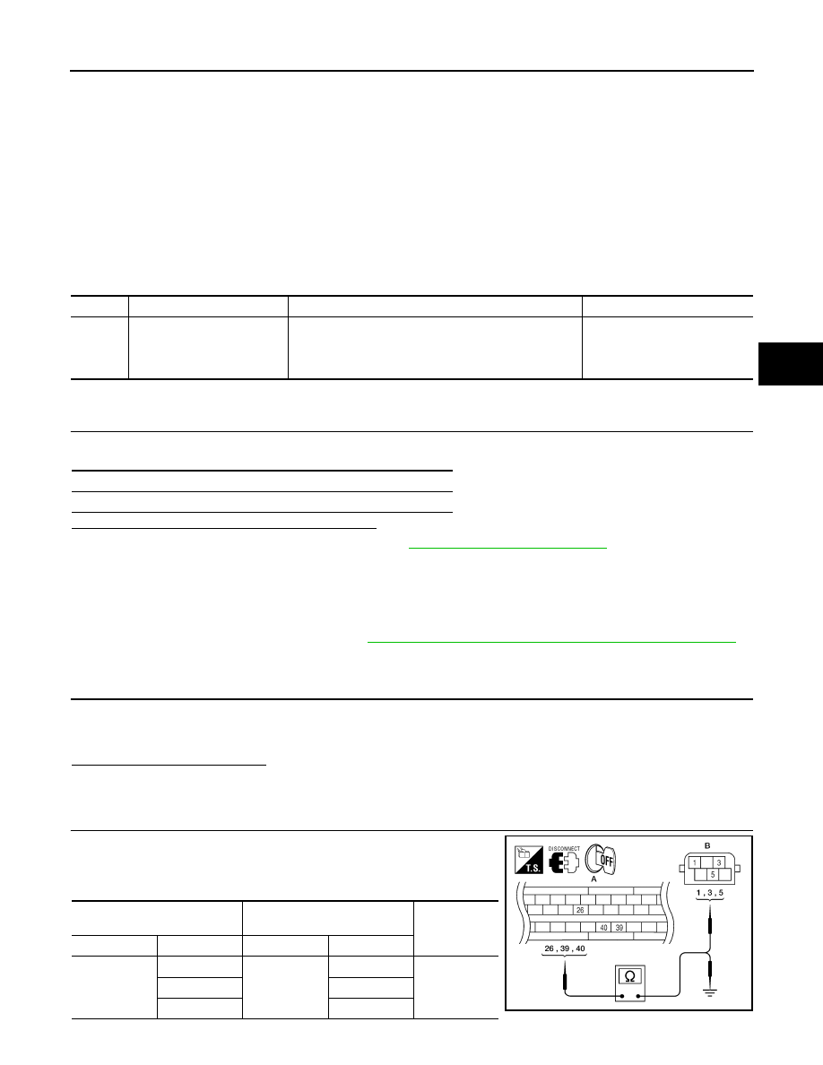
1. Measure the continuity between ABS actuator and electric unit
(control unit) connector E125 (A) and delta stroke sensor con-
nector E114 (B).
DTC
Display item
Malfunction detected condition
Possible cause
C1179
ABS DELTA S SEN NG
Delta stroke sensor is malfunctioning, or signal line of
delta stroke sensor is open or shorted.
• Harness or connector
• Delta stroke sensor
• ABS actuator and electric unit
(control unit)
Self-diagnosis results
ABS DELTA S SEN NG
ABS actuator and electric unit
(control unit)
Delta stroke sensor
Continuity
Connector
Terminal
Connector
Terminal
E125 (A)
26
E114 (B)
1
Yes
39
3
40
5
AWFIA0029ZZ

BRC-76
< COMPONENT DIAGNOSIS >
[VDC/TCS/ABS]
C1179 ABS DELTA S SEN NG
2. Measure the continuity between ABS actuator and electric unit (control unit) connector E125 (A) and body
ground.
Is the inspection result normal?
YES
>> GO TO 3
NO
>> Repair or replace harness or connector.
3.
DELTA STROKE SENSOR INSPECTION
1. Connect the delta stroke sensor and ABS actuator and electric unit (control unit) connectors.
2. Perform the delta stroke sensor component inspection. Refer to
BRC-76, "Component Inspection"
Is the inspection result normal?
YES
>> Replace the ABS actuator and electric unit (control unit). Refer to
.
NO
>> Replace the delta stroke sensor.
Component Inspection
INFOID:0000000005148055
1.
CHECK DATA MONITOR
Use “DATA MONITOR” to check if the status of “DELTA S SEN” is normal.
Is the inspection result normal?
YES
>> Inspection End
NO
>> Go to diagnosis procedure. Refer to
Special Repair Requirement
INFOID:0000000005194922
1.
ADJUSTMENT OF STEERING ANGLE SENSOR NEUTRAL POSITION
Always perform neutral position adjustment for the steering angle sensor when replacing the ABS actuator
and electric unit (control unit). Refer to
BRC-8, "ADJUSTMENT OF STEERING ANGLE SENSOR NEUTRAL
.
>> GO TO 2
2.
CALIBRATION OF DECEL G SENSOR
Always perform calibration of decel G sensor when replacing the ABS actuator and electric unit (control unit).
BRC-9, "CALIBRATION OF DECEL G SENSOR : Description"
>> END
ABS actuator and electric unit (control
unit)
—
Continuity
Connector
Terminal
E125 (A)
26
Ground
No
39
40
Condition
DELTA S SEN
(DATA MONITOR)
When brake pedal is applied.
1.05–1.80 mm
When brake pedal is released.
0.00 mm (+0.6/-0.4)
Нет комментариевНе стесняйтесь поделиться с нами вашим ценным мнением.
Текст