Infiniti QX56 (JA60). Manual — part 305
TRANSFER ASSEMBLY
DLN-143
< DISASSEMBLY AND ASSEMBLY >
[ATX14B]
C
E
F
G
H
I
J
K
L
M
A
B
DLN
N
O
P
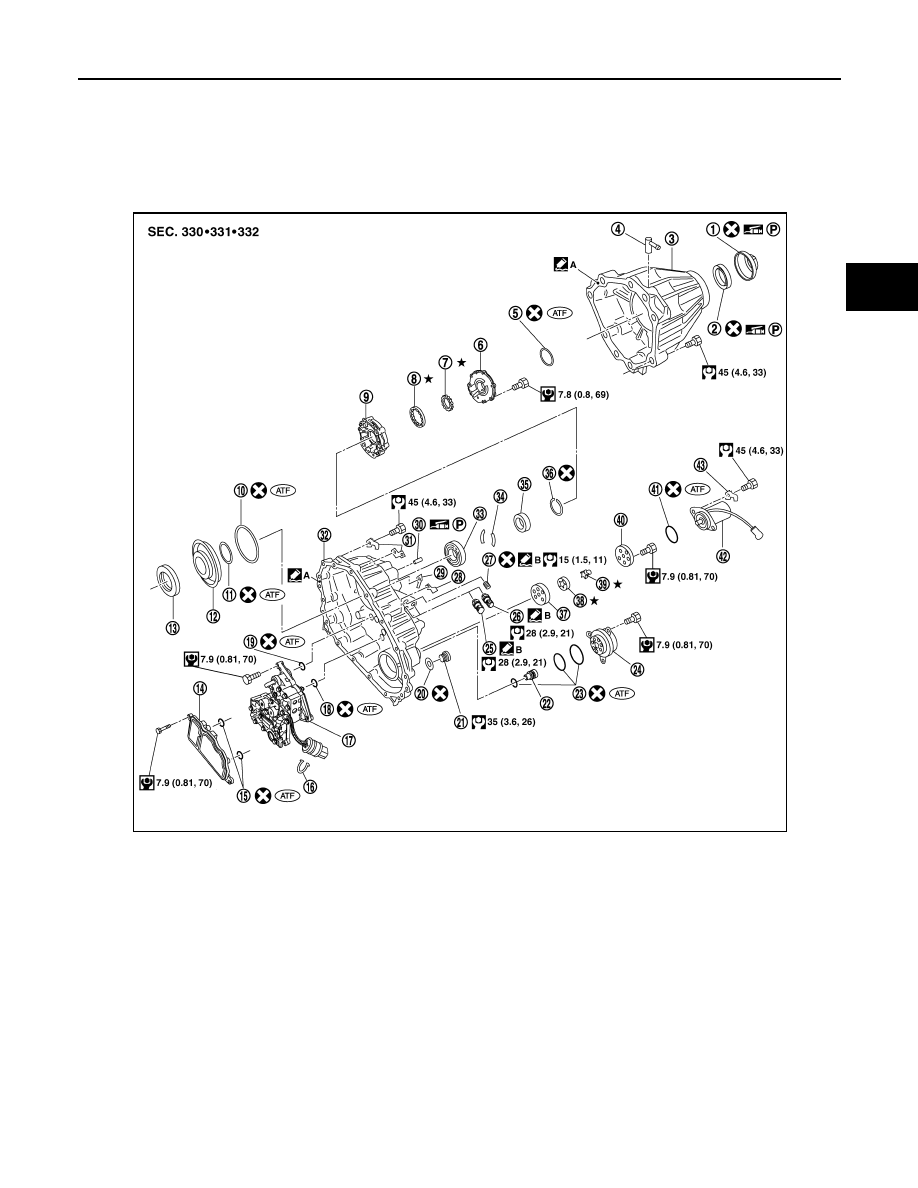
40.
Retaining plate
41.
Driven plate (10 sheet)
42.
Drive plate (10 sheet)
43.
Return spring assembly
44.
Press flange
45.
Thrust needle bearing
46.
Snap ring
47.
Retaining pin
48.
L-H fork
49.
2-4 fork
50.
Shift fork spring
51.
Fork guide
52.
Retainer pin
53.
Shift rod
1.
Dust cover
2.
Rear oil seal
3.
Rear case
4.
Breather tube
5.
Seal ring
6.
Main oil pump cover
7.
Inner gear
8.
Outer gear
9.
Main oil pump housing
10.
D-ring
11. D-ring
12.
Clutch piston
13.
Thrust needle bearing race
14. Oil strainer
15.
O-ring
16.
Snap ring
17. Control valve assembly
18.
Lip seal (large 5 pieces)
19.
Lip seal (small 2 pieces)
20. Gasket
21.
Filler plug
22.
Oil filter stud
23. O-ring
24.
Oil filter
25
ATP switch
26. Neutral-4LO switch
27.
Oil pressure check plug
28.
Harness bracket
29. Air breather hose clamp
30.
Stem bleeder
31.
Harness bracket
32. Center case
33.
Mainshaft rear bearing
34.
C-ring
35. Washer holder
36.
Snap ring
37.
Sub oil pump housing
38. Outer gear
39.
Inner gear
WDIA0302E
DLN-144
< DISASSEMBLY AND ASSEMBLY >
[ATX14B]
TRANSFER ASSEMBLY
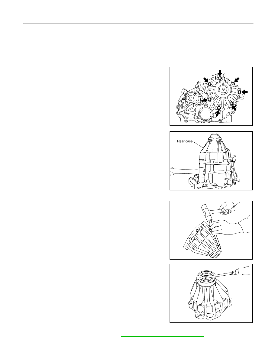
DISASSEMBLY
Rear Case
1. Remove the rear case bolts.
2. Remove the rear case from the center case.
3. Remove the dust cover using suitable tool.
4. Remove the rear oil seal using suitable tool.
CAUTION:
Do not damage rear case.
5. Remove the breather tube.
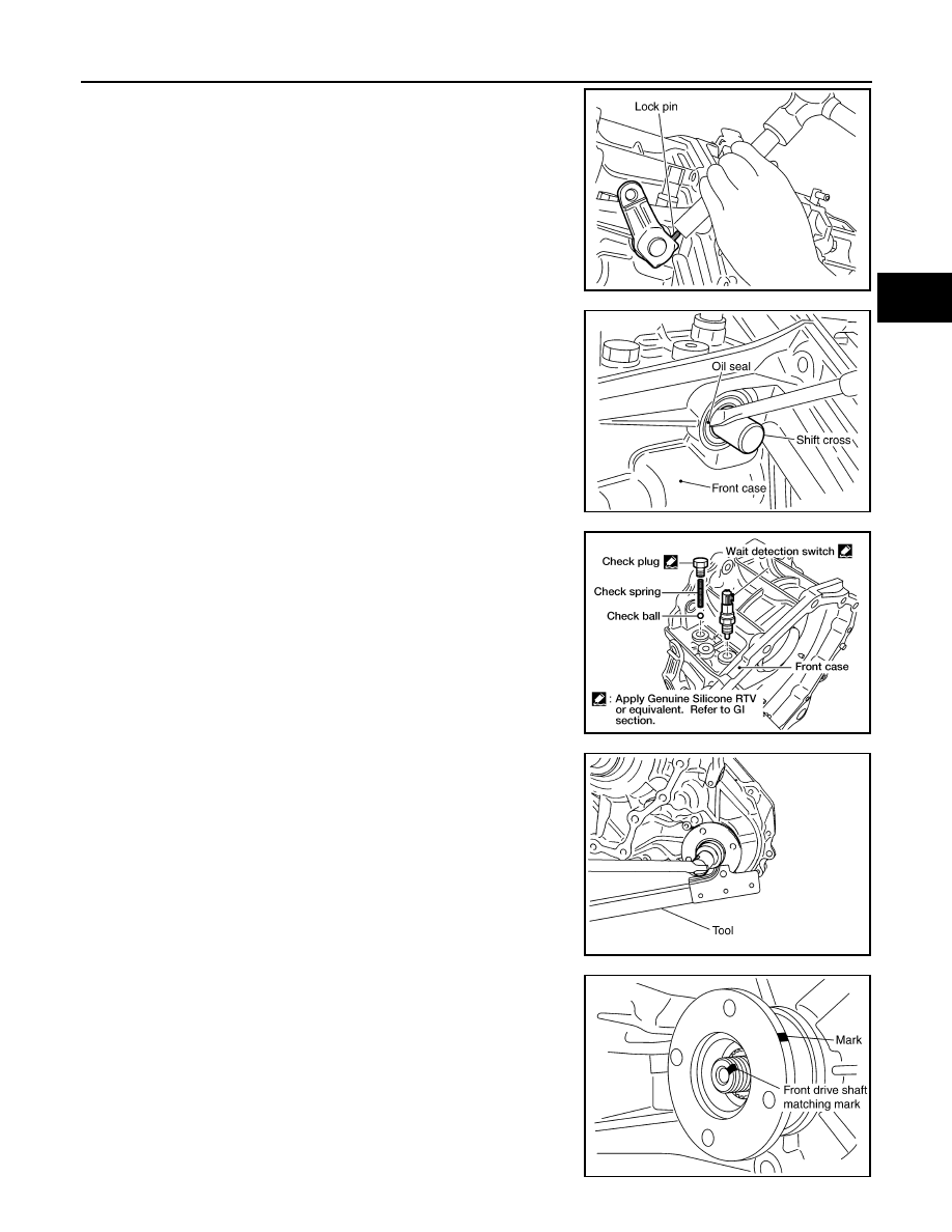
Front Case
1. Remove the rear case assembly. Refer to
DLN-142, "Disassembly and Assembly"
2. Remove the lock pin nut.
40.
Sub oil pump cover
41. O-ring
42.
Transfer motor
43.
Connector bracket
A.
Apply Genuine Anaerobic Liquid
Gasket, Three Bond TB1133C or
equivalent.
B.
Apply Genuine Liquid Gasket,
Three Bond TB1215 or equiva-
lent.
SDIA2092E
SDIA2093E
SDIA2094E
SDIA2095E
TRANSFER ASSEMBLY
DLN-145
< DISASSEMBLY AND ASSEMBLY >
[ATX14B]
C
E
F
G
H
I
J
K
L
M
A
B
DLN
N
O
P
3. Remove the lock pin using suitable tool.
4. Remove the shift lever.
5. Remove the side oil seal from the front case using suitable tool.
CAUTION:
Do not damage front case or shift cross.
6. Remove the check plug, check spring and check ball.
7. Remove the wait detection switch.
8. Remove the self-lock nut from the companion flange using suit-
able tool.
9. Put a matching mark on top of the front drive shaft thread in line
with the mark on the companion flange.
CAUTION:
Use paint to make the matching mark on the front drive
shaft thread. Never damage the front drive shaft.
SDIA2150E
SDIA2166E
WDIA0196E
SDIA2841E
SDIA2779E
DLN-146
< DISASSEMBLY AND ASSEMBLY >
[ATX14B]
TRANSFER ASSEMBLY
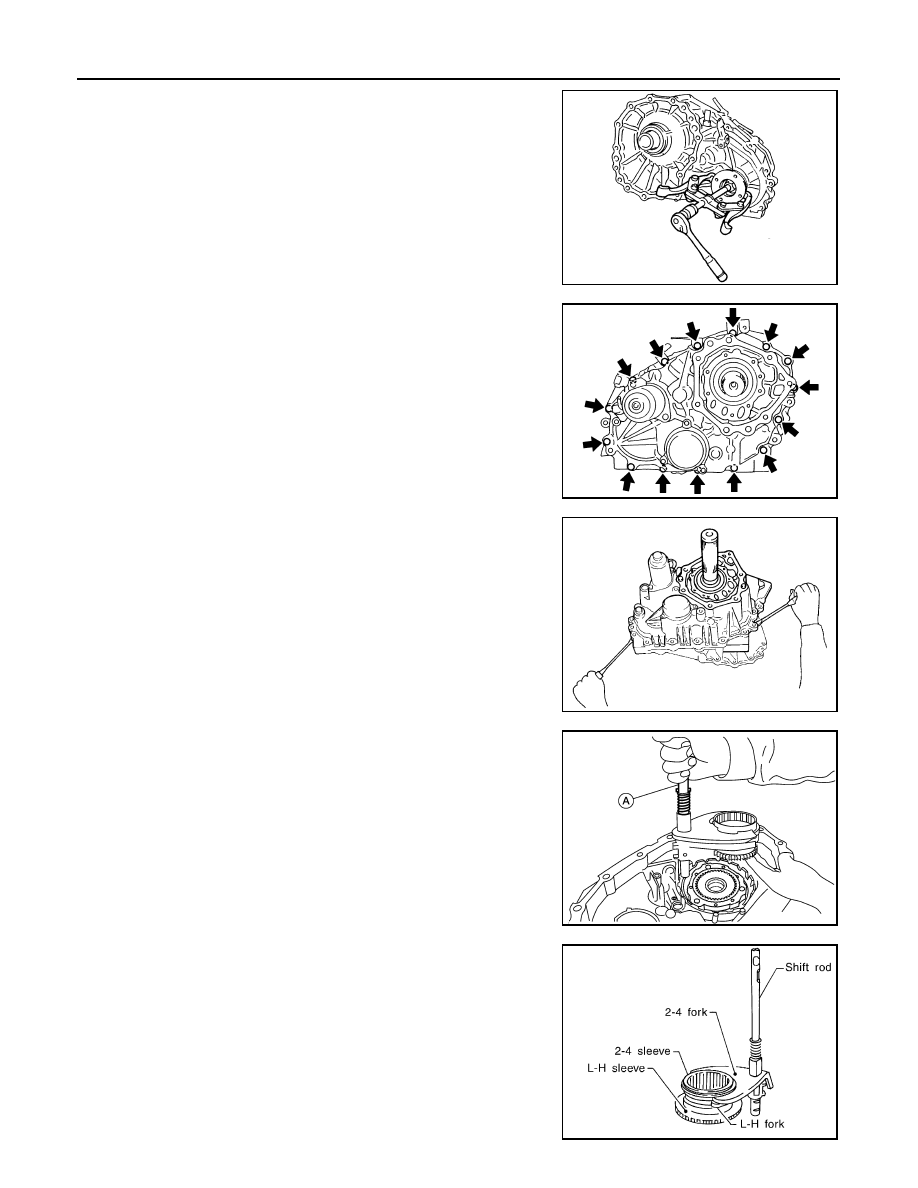
10. Remove the companion flange using suitable tool.
11. Remove the center case bolts, harness bracket and air breather.
12. Remove the filler plug and gasket.
13. Separate the center case from the front case. Then remove the
center case from the front case by prying it up using suitable
tool.
CAUTION:
Do not damage the mating surfaces.
14. Remove the shift rod components together with the 2-4 sleeve
and L-H sleeve.
15. Remove the shift cross from the front case, using shift rod (A).
16. Remove the 2-4 sleeve and L-H sleeve from the 2-4 fork and L-
H fork respectively.
WDIA0133E
SDIA2100E
SDIA2101E
AWDIA0015ZZ
SMT992C
Нет комментариевНе стесняйтесь поделиться с нами вашим ценным мнением.
Текст