Infiniti QX56 (JA60). Manual — part 851
SEC-50
< COMPONENT DIAGNOSIS >
[WITH INTELLIGENT KEY SYSTEM]
POWER SUPPLY AND GROUND CIRCUIT
YES
>> Replace the blown fuse or fusible link after repairing the affected circuit.
NO
>> GO TO 2
2.
CHECK POWER SUPPLY CIRCUIT
1. Turn ignition switch OFF.
2. Disconnect BCM.
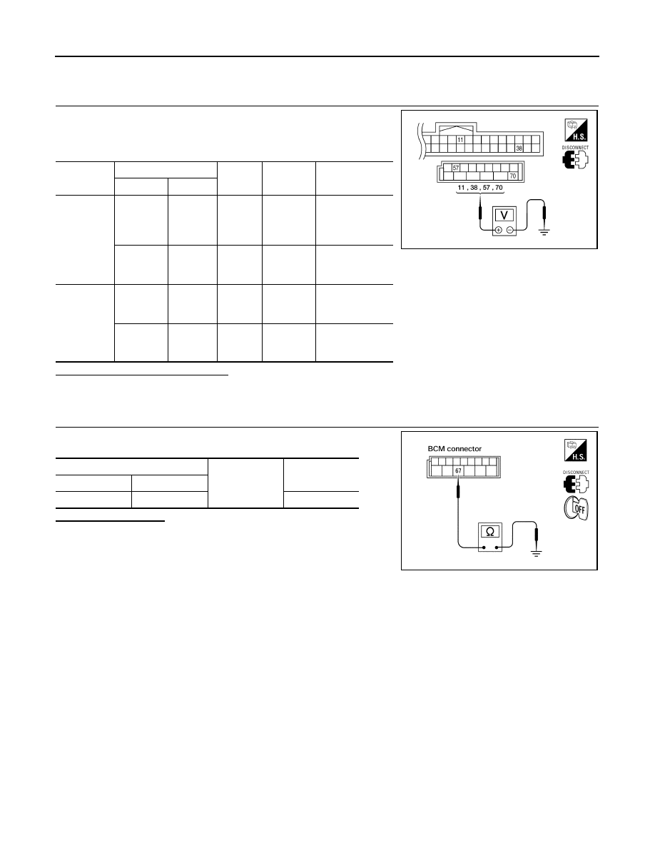
3. Check voltage between BCM harness connector and ground.
Is the measurement value normal?
YES
>> GO TO 3
NO
>> Repair or replace harness.
3.
CHECK GROUND CIRCUIT
Check continuity between BCM harness connector and ground.
Does continuity exist?
YES
>> Inspection End.
NO
>> Repair or replace harness.
Connector
Terminals
Power
source
Condition
Voltage (V) (Ap-
prox.)
(+)
(-)
M18
11
Ground
ACC
power
supply
Ignition
switch
ACC or
ON
Battery voltage
38
Ground
Ignition
power
supply
Ignition
switch ON
or START
Battery voltage
M20
57
Ground
Battery
power
supply
Ignition
switch
OFF
Battery voltage
70
Ground
Battery
power
supply
Ignition
switch
OFF
Battery voltage
LIIA2415E
BCM
Ground
Continuity
Connector
Terminal
M20
67
Yes
LIIA0915E
KEY CYLINDER SWITCH
SEC-51
< COMPONENT DIAGNOSIS >
[WITH INTELLIGENT KEY SYSTEM]
C
D
E
F
G
H
I
J
L
M
A
B
SEC
N
O
P
KEY CYLINDER SWITCH
Description
INFOID:0000000005147120
The main power window and door lock/unlock switch detects condition of the door key cylinder switch and
transmits to BCM as the LOCK or UNLOCK signal.
Component Function Check
INFOID:0000000005147121
1.
CHECK DOOR KEY CYLINDER SWITCH INPUT SIGNAL
Check "KEY CYL LK-SW" AND "KEY CYL UN-SW" in DATA MONITOR mode for “POWER DOOR LOCK
SYSTEM” with CONSULT-III.
Is the inspection result normal?
YES
>> Key cylinder switch is OK.
NO
>> Refer to
Diagnosis Procedure
INFOID:0000000005147122
Regarding Wiring Diagram information, refer to
SEC-69, "Wiring Diagram - VEHICLE SECURITY SYSTEM"
1.
CHECK DOOR KEY CYLINDER SWITCH LH
With CONSULT-III
Check front door lock assembly LH (key cylinder switch) ("KEY CYL LK-SW") and ("KEY CYL UN-SW) in
DATA MONITOR mode with CONSULT–III.
• When key inserted in left front key cylinder is turned to LOCK:
• When key inserted in left front key cylinder is turned to UNLOCK:
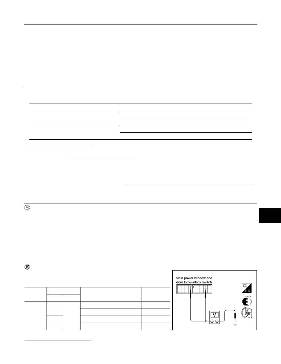
Without CONSULT-III
Check voltage between main power window and door lock/unlock
switch connector D7 terminals 4, 6 and ground.
Is the inspection result normal?
YES
>> Key cylinder switch signal is OK.
Monitor item
Condition
KEY CYL LK-SW
Lock
: ON
Neutral / Unlock
: OFF
KEY CYL UN-SW
Unlock
: ON
Neutral / Lock
: OFF
KEY CYL LK-SW
: ON
KEY CYL UN-SW
: ON
Connector
Terminals
Condition of left front key cylinder
Voltage (V)
(Approx.)
(+)
(–)
D7
4
Ground
Neutral/Unlock
5
Lock
0
6
Neutral/Lock
5
Unlock
0
LIIA0566E
SEC-52
< COMPONENT DIAGNOSIS >
[WITH INTELLIGENT KEY SYSTEM]
KEY CYLINDER SWITCH
NO
>> GO TO 2
2.
CHECK DOOR KEY CYLINDER SWITCH LH GROUND HARNESS
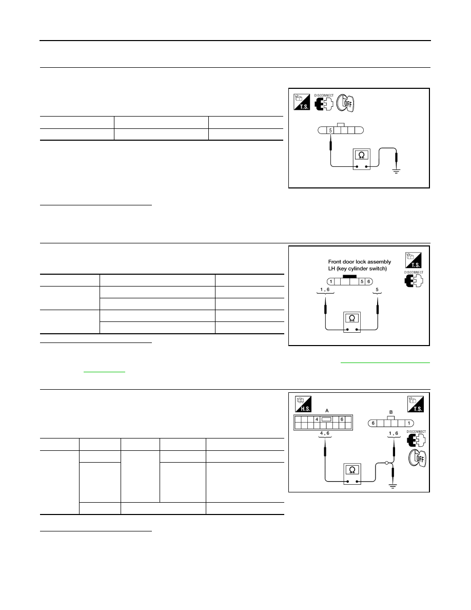
1. Turn ignition switch OFF.
2. Disconnect front door lock assembly LH (key cylinder switch).
3. Check continuity between front door lock assembly LH (key cyl-
inder switch) connector (A) D14 terminal 5 and body ground.
Is the inspection result normal?
YES
>> GO TO 3
NO
>> Repair or replace harness.
3.
CHECK DOOR KEY CYLINDER SWITCH LH
Check continuity between front door lock assembly LH (key cylinder
switch) terminals.
Is the inspection result normal?
YES
>> GO TO 4
NO
>> Replace front door lock assembly LH (key cylinder switch). Refer to
4.
CHECK DOOR KEY CYLINDER HARNESS
Check continuity between main power window and door lock/unlock
switch connector (A) D7 terminals 4, 6 and front door lock assembly
LH (key cylinder switch) connector (B) D14 terminals 1, 6 and body
ground.
Is the inspection result normal?
YES
>> Replace main power window and door lock/unlock switch.
NO
>> Repair or replace harness.
Connector
Terminals
Continuity
D14
5 – Ground
Yes
WIIA0813E
Terminals
Condition
Continuity
1 – 5
Key is turned to UNLOCK or neutral.
No
Key is turned to LOCK.
Yes
5 – 6
Key is turned to LOCK or neutral.
No
Key is turned to UNLOCK.
Yes
LIIA1573E
Connector
Terminals
Connector
Terminals
Continuity
A: Main
power win-
dow and
door lock/
unlock
switch
4
B: Front
door lock
assembly
LH (key
cylinder
switch)
1
Yes
6
6
Yes
4, 6
Ground
No
WIIA0814E
IGNITION KNOB SWITCH
SEC-53
< COMPONENT DIAGNOSIS >
[WITH INTELLIGENT KEY SYSTEM]
C
D
E
F
G
H
I
J
L
M
A
B
SEC
N
O
P
IGNITION KNOB SWITCH
Ignition Knob Switch Check
INFOID:0000000005147123
Regarding Wiring Diagram information, refer to
SEC-94, "Wiring Diagram - INTELLIGENT KEY SYSTEM/
.
1.
CHECK IGNITION KNOB SWITCH
With CONSULT-III
Display “PUSH SW” on DATA MONITOR screen, and check if ON/OFF display is linked to ignition switch oper-
ation.
Without CONSULT-III
1. Turn ignition switch OFF.
2. Disconnect Intelligent Key unit connector.
3. Check voltage between Intelligent Key unit harness connector
M70 terminal 27 and ground.
Is the inspection result normal?
YES
>> Ignition knob switch is OK.
NO
>> GO TO 2
2.
CHECK IGNITION KNOB SWITCH POWER SUPPLY CIRCUIT
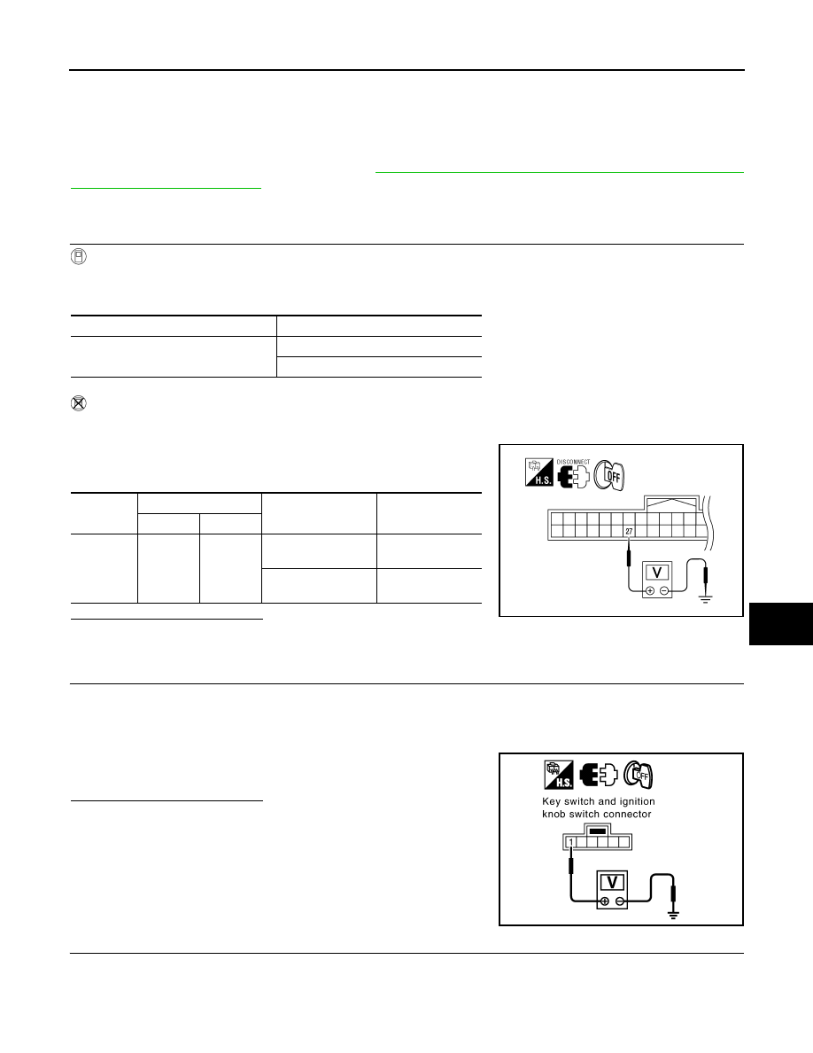
1. Turn ignition switch OFF.
2. Disconnect key switch and ignition knob switch connector.
3. Check voltage between key switch and ignition knob switch harness connector M12 terminal 1 and
ground.
Is the inspection result normal?
YES
>> GO TO 3
NO
>> Repair or replace key switch and ignition knob switch
power supply circuit.
3.
CHECK IGNITION KNOB SWITCH OPERATION
Check continuity between key switch and ignition knob switch terminals 1 and 2.
Monitor item
Condition
PUSH SW
Ignition switch is pushed: ON
Ignition switch is released: OFF
Connector
Terminals
Condition
Voltage (V)
(Approx.)
(+)
(–)
M70
27
Ground
Ignition switch is
pushed
Battery voltage
Ignition switch is re-
leased
0
WIIA1175E
1 - Ground
: Battery voltage
PIIB4257E
Нет комментариевНе стесняйтесь поделиться с нами вашим ценным мнением.
Текст