Infiniti QX56 (JA60). Manual — part 468
EM-26
< ON-VEHICLE REPAIR >
INTAKE MANIFOLD
INTAKE MANIFOLD
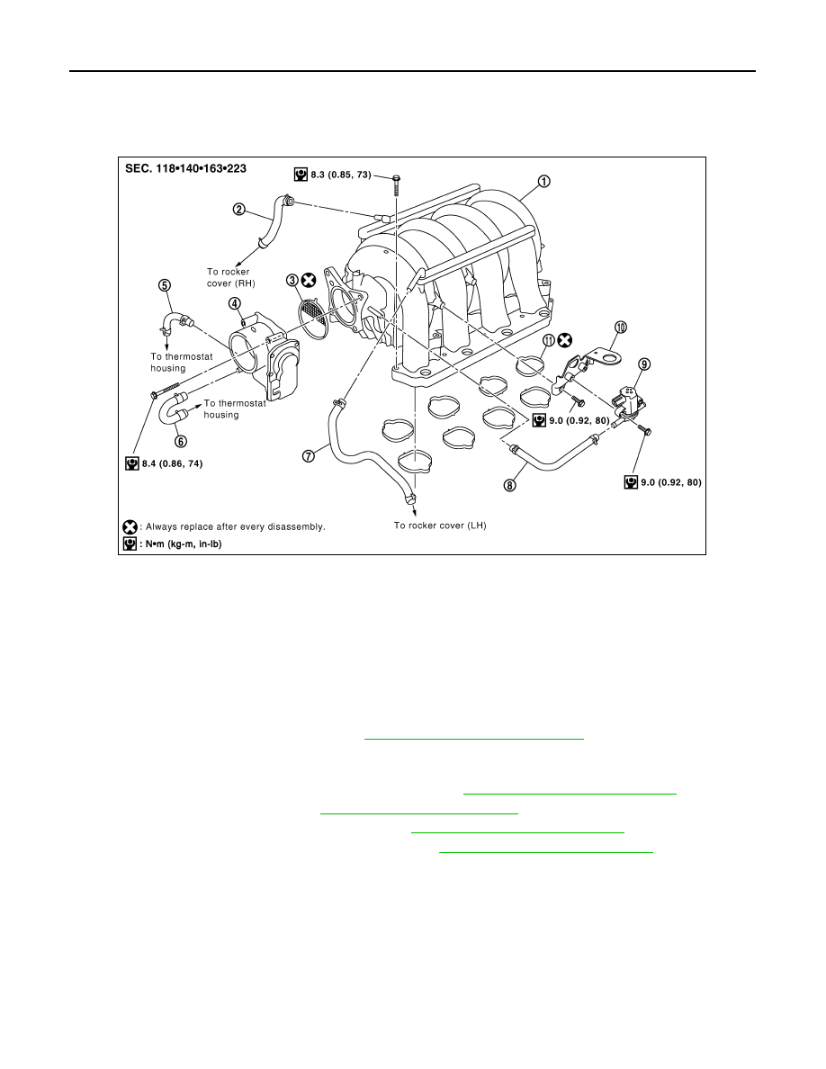
Exploded View
INFOID:0000000005148987
Removal and Installation
INFOID:0000000005148988
REMOVAL
1. Partially drain the engine coolant. Refer to
CO-11, "Changing Engine Coolant"
WARNING:
To avoid the danger of being scalded, never drain the engine coolant when the engine is hot.
2. Remove the engine room cover using power tool. Refer to
EM-24, "Removal and Installation"
.
3. Release the fuel pressure. Refer to
4. Disconnect the negative battery terminal. Refer to
PG-74, "Removal and Installation"
5. Remove the air duct and resonator assembly. Refer to
EM-25, "Removal and Installation"
.
1.
Intake manifold
2.
PCV hose
3.
Gasket
4.
Electric throttle control actuator
5.
Water hose
6.
Water hose
7.
PCV hose
8.
EVAP hose
9.
EVAP canister purge control solenoid
valve
10.
Bracket
11.
Gasket
KBIA2461E
INTAKE MANIFOLD
EM-27
< ON-VEHICLE REPAIR >
C
D
E
F
G
H
I
J
K
L
M
A
EM
N
P
O
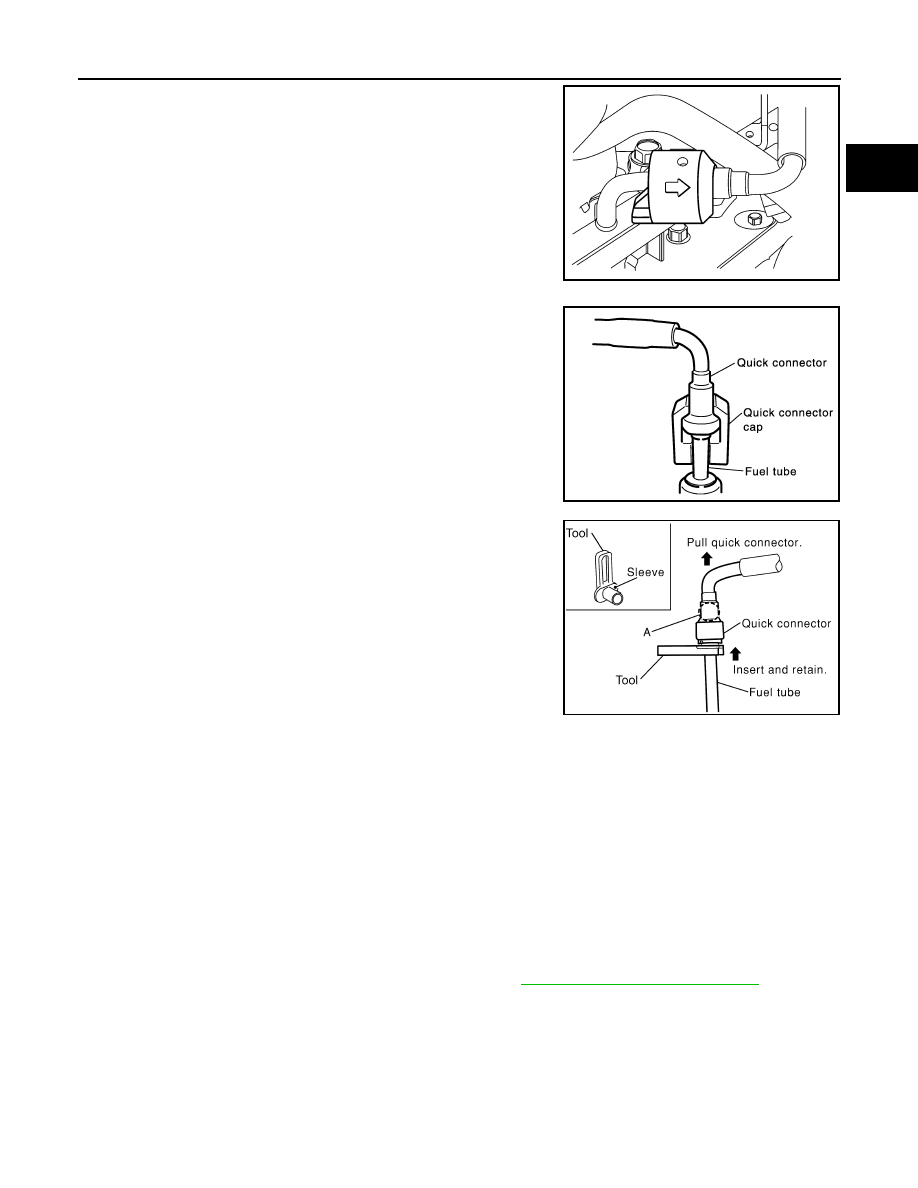
6. Disconnect the fuel tube quick connector on the engine side in
the following steps.
a. Remove quick connector cap (engine side only).
b. With the sleeve side of Tool facing quick connector, install Tool
onto fuel tube.
c. Insert Tool into quick connector until sleeve contacts and goes
no further. Hold the Tool in that position.
CAUTION:
Inserting the Tool hard will not disconnect quick connector.
Hold Tool where it contacts and goes no further.
d. Draw and pull out quick connector straight from fuel tube.
CAUTION:
• Pull quick connector holding "A" position in illustration.
• Do not pull with lateral force applied. O-ring inside quick connector may be damaged.
• Prepare container and cloth beforehand as fuel will leak out.
• Avoid fire and sparks.
• Be sure to cover openings of disconnected pipes with plug or plastic bag to avoid fuel leakage
and entry of foreign materials.
7. Remove or disconnect harnesses, brackets, vacuum hose, vacuum gallery and PCV hose and tube from
intake manifold.
8. Remove the EVAP canister purge control solenoid valve, if necessary.
9. Remove electric throttle control actuator by loosening bolts diagonally.
CAUTION:
• Handle carefully to avoid any damage to the electric throttle control actuator.
• Do not disassemble.
10. Remove the fuel injectors and fuel tube assembly. Refer to
EM-40, "Removal and Installation"
LBIA0395E
SBIA0354E
Tool number
: 16441 6N210 (J-45488)
WBIA0604E
EM-28
< ON-VEHICLE REPAIR >
INTAKE MANIFOLD
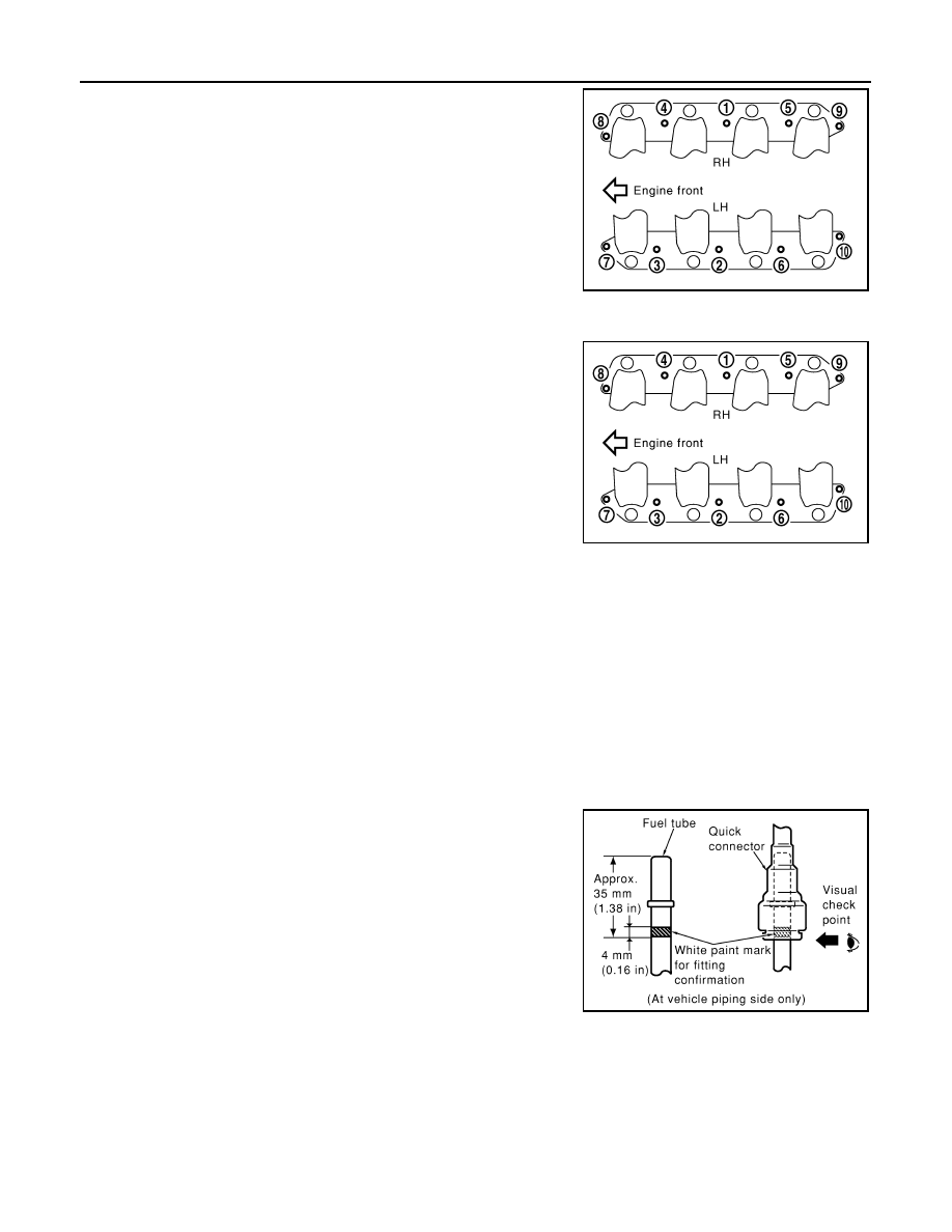
11. Loosen the bolts in reverse order shown using power tool.
12. Remove the intake manifold.
CAUTION:
Cover engine openings to avoid entry of foreign materials.
• Clean all gasket mating surfaces, do not reuse gaskets.
INSTALLATION
Installation is in the reverse order of removal.
• Tighten the intake manifold bolts in numerical order as shown.
• Install the EVAP canister purge control solenoid valve connector with it facing front of engine.
• Tighten the electronic throttle control actuator bolts of the electric throttle control actuator equally and diago-
nally in several steps.
• After installation perform procedure in "INSPECTION AFTER INSTALLATION".
• Install the water hose so that its overlap width for connection is between 27 mm (1.06 in) and 32 mm (1.26
in) (target: 27 mm 1.06 in).
Connecting Quick Connector of Fuel Tube
Install quick connector as follows (the steps are the same for quick connectors on both engine side and vehi-
cle side except for the quick connector cap).
1. Make sure no foreign substances are deposited in and around tube and quick connector, and they are not
damaged.
2. Thinly apply new engine oil around the fuel tube from tip end to the spool end.
3. Align center to insert quick connector straight into fuel tube.
• Insert until the paint mark for engagement identification (white)
goes completely inside quick connector so that you cannot see
it from the straight side of the connected part. Use a mirror to
check this where it is not possible to view directly from the
straight side, such as quick connector on vehicle side.
KBIA2462E
KBIA2462E
PBIC0017E
INTAKE MANIFOLD
EM-29
< ON-VEHICLE REPAIR >
C
D
E
F
G
H
I
J
K
L
M
A
EM
N
P
O
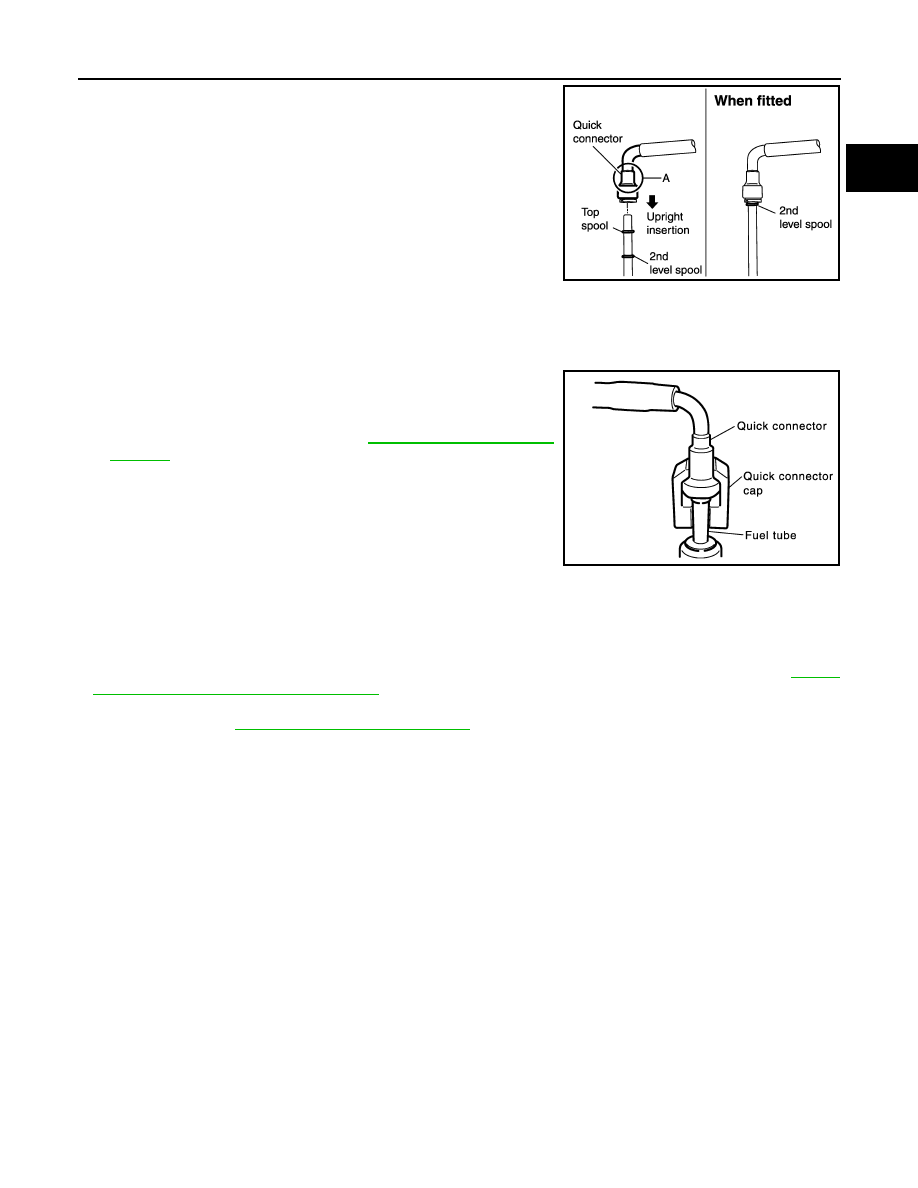
• Insert fuel tube into quick connector until top spool is com-
pletely inside quick connector, and 2nd level spool exposes
right below quick connector on engine side.
CAUTION:
• Hold "A" position in illustration when inserting fuel tube
into quick connector.
• Carefully align center to avoid inclined insertion to pre-
vent damage to O-ring inside quick connector.
• Insert until you hear a "click" sound and actually feel the
engagement.
• To avoid misidentification of engagement with a similar
sound, be sure to perform the next step.
4. Pull quick connector by hand holding "A" position. Make sure it is completely engaged (connected) so that
it does not come out from fuel tube.
NOTE:
Recommended pulling force is 50 N (5.1 kg, 11.2 lb).
5. Install the quick connector cap on the quick connector joint (on
engine side only).
6. Install the fuel hose and tube to hose clamps.
7. Refill the engine coolant. Refer to
INSPECTION AFTER INSTALLATION
• After installing fuel tubes, make sure there is no fuel leakage at connections in the following steps.
- Apply fuel pressure to fuel lines by turning ignition switch ON (with engine stopped). Then check for fuel
leaks at connections.
- Start the engine and rev it up and check for fuel leaks at the connections.
• Perform procedures for “Throttle Valve Closed Position Learning” after finishing repairs. Refer to
"Throttle Valve Closed Position Learning"
• If electric throttle control actuator is replaced, perform procedures for “Idle Air Volume Learning” after finish-
ing repairs. Refer to
EC-18, "Idle Air Volume Learning"
.
KBIA0272E
SBIA0354E
Нет комментариевНе стесняйтесь поделиться с нами вашим ценным мнением.
Текст