Infiniti QX56 (JA60). Manual — part 466
EM-18
< ON-VEHICLE MAINTENANCE >
CAMSHAFT VALVE CLEARANCE
CAMSHAFT VALVE CLEARANCE
Valve Clearance
INFOID:0000000005148982
INSPECTION
NOTE:
Perform the following inspection after removal, installation or replacement of camshaft or valve-related parts,
or if there are unusual engine conditions due to changes in valve clearance over time (starting, idling, and/or
noise).
1. Warm up the engine. Then stop the engine.
2. Remove the engine room cover. Refer to
EM-24, "Removal and Installation"
3. Remove the air cleaner and air duct assembly. Refer to
EM-25, "Removal and Installation"
4. Remove the RH bank and LH bank rocker covers using power tool. Refer to
.
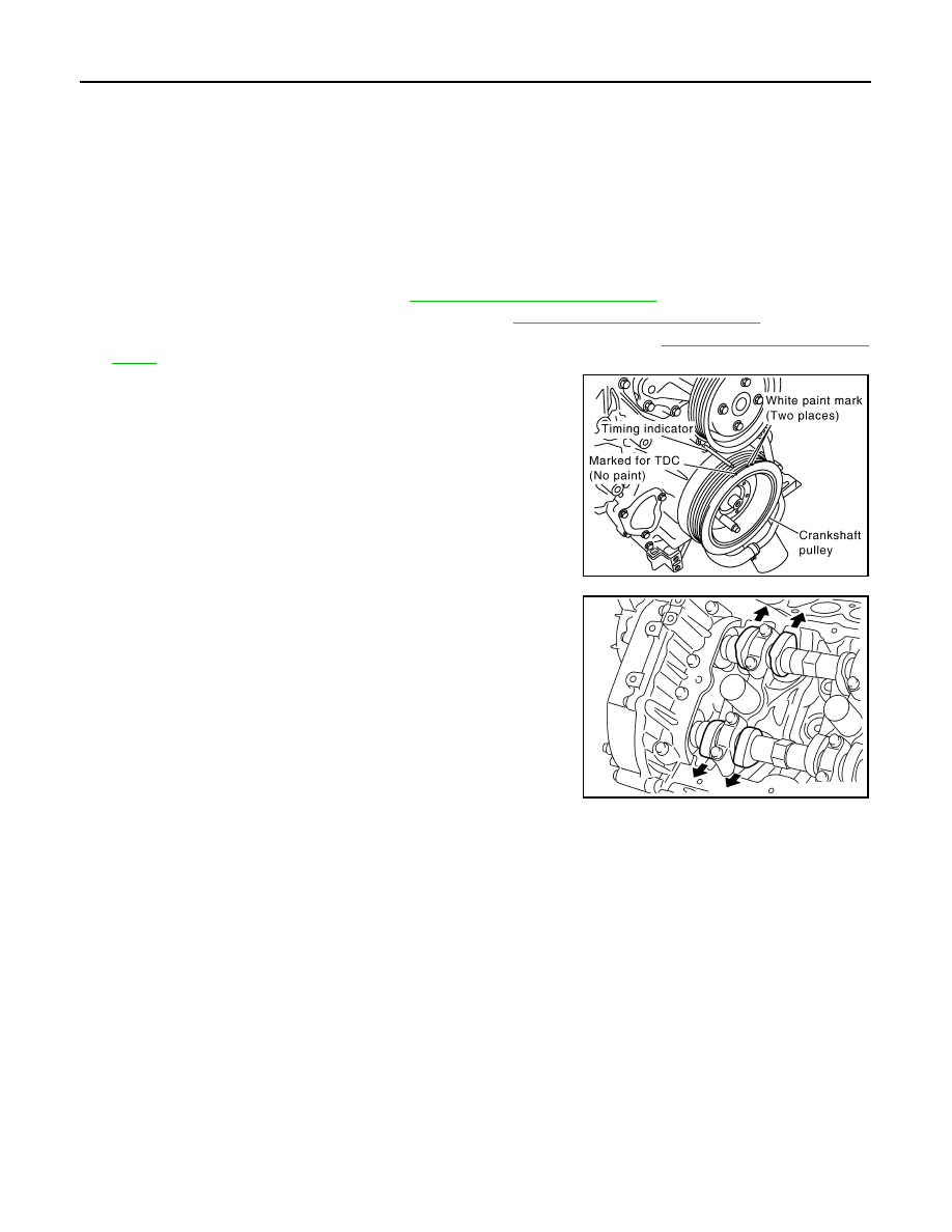
5. Turn the crankshaft pulley in the normal direction (clockwise
when viewed from engine front) to align TDC identification notch
(without paint mark) with timing indicator.
6. At this time, make sure both the intake and exhaust cam noses
of No. 1 cylinder (top front on LH bank) face outside.
• If they do not face outside, turn crankshaft pulley once more.
KBIA2476E
KBIA0400J
CAMSHAFT VALVE CLEARANCE
EM-19
< ON-VEHICLE MAINTENANCE >
C
D
E
F
G
H
I
J
K
L
M
A
EM
N
P
O
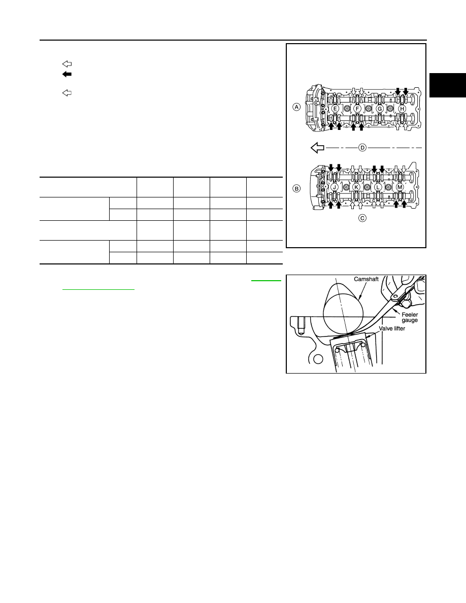
7. Measure valve clearances at the locations marked “
×” as shown
in the table below (locations indicated with black arrow).
•
: Engine front
•
(black): Measurable at No.1 cylinder compression top dead
center
•
(white): Measurable at No. 3 cylinder compression top
dead center
• A: RH
• B: LH
• C: Exhaust
• D: Intake
NOTE:
Firing order 1-8-7-3-6-5-4-2
• No. 1 cylinder compression TDC
• Measure valve clearance using suitable tool. Refer to
CAUTION:
If the inspection was carried out with a cold engine, make
sure the values with a fully warmed up engine are still
within specifications.
8. Turn the crankshaft pulley clockwise 270
° from the position of No. 1 cylinder compression TDC to obtain
No. 3 cylinder compression TDC.
Measuring position (RH bank)
No. 2 cyl
(E)
No. 4 cyl
(F)
No. 6 cyl
(G)
No. 8 cyl
(H)
No. 1 cylinder at TDC
EXH
×
INT
×
×
Measuring position (LH bank)
No. 1 cyl
(J)
No. 3 cyl
(K)
No. 5 cyl
(L)
No. 7 cyl
(M)
No. 1 cylinder at TDC
INT
×
×
EXH
×
×
WBIA0713E
KBIA0185E
EM-20
< ON-VEHICLE MAINTENANCE >
CAMSHAFT VALVE CLEARANCE
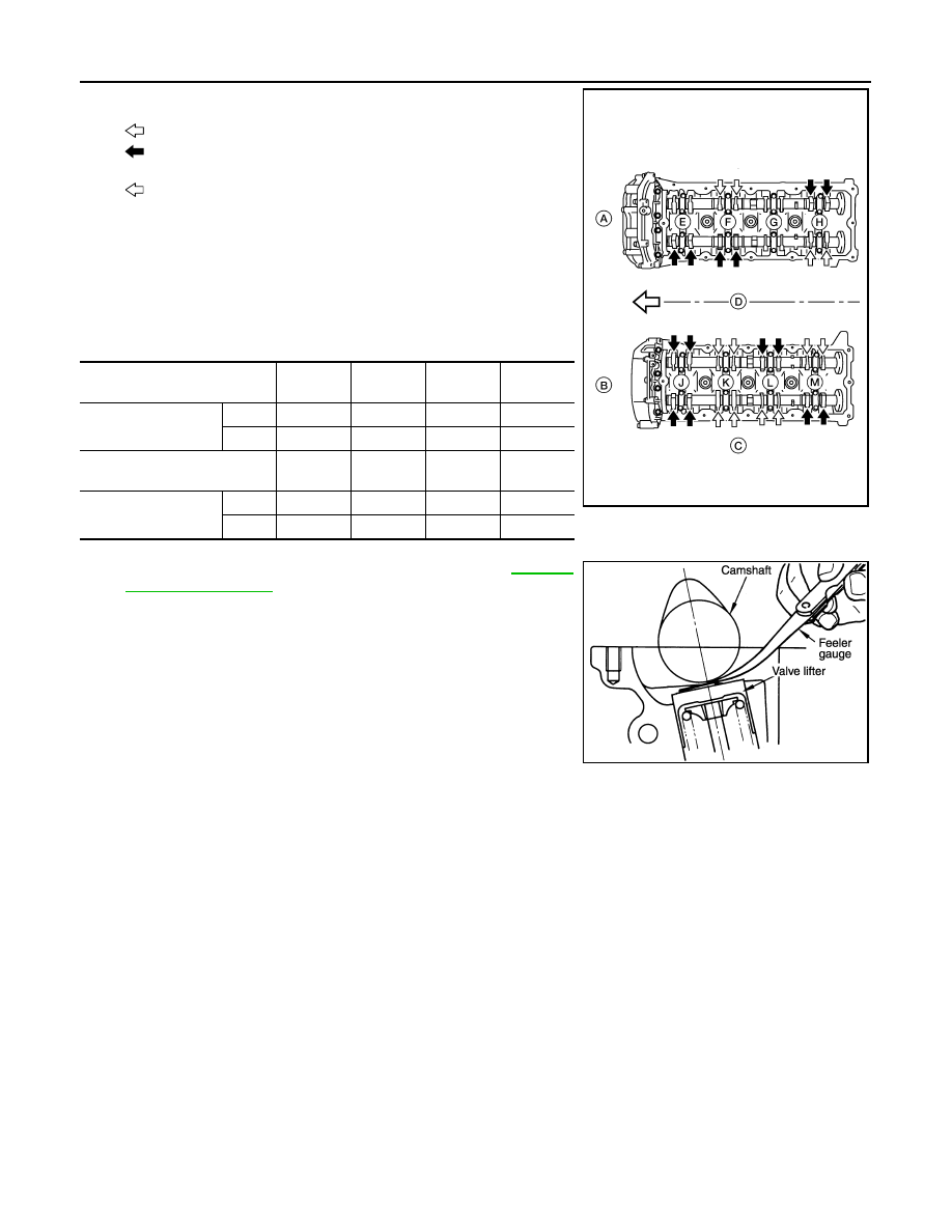
9. Measure valve clearances at the locations marked “
×” as shown
in the table below (locations indicated with white arrow).
•
: Engine front
•
(black): Measurable at No.1 cylinder compression top dead
center
•
(white): Measurable at No. 3 cylinder compression top
dead center
• A: RH
• B: LH
• C: Exhaust
• D: Intake
NOTE:
Firing order 1-8-7-3-6-5-4-2
• No. 3 cylinder compression TDC
• Measure valve clearance using suitable tool. Refer to
CAUTION:
If the inspection was carried out with a cold engine, make
sure the values with a fully warmed up engine are still
within specifications.
Measuring position (RH bank)
No. 2 cyl
(E)
No. 4 cyl
(F)
No. 6 cyl
(G)
No. 8 cyl
(H)
No. 3 cylinder at TDC
EXH
×
INT
×
Measuring position (LH bank)
No. 1 cyl
(J)
No. 3 cyl
(K)
No. 5 cyl
(L)
No. 7 cyl
(M)
No. 3 cylinder at TDC
INT
×
×
EXH
×
×
WBIA0713E
KBIA0185E
CAMSHAFT VALVE CLEARANCE
EM-21
< ON-VEHICLE MAINTENANCE >
C
D
E
F
G
H
I
J
K
L
M
A
EM
N
P
O
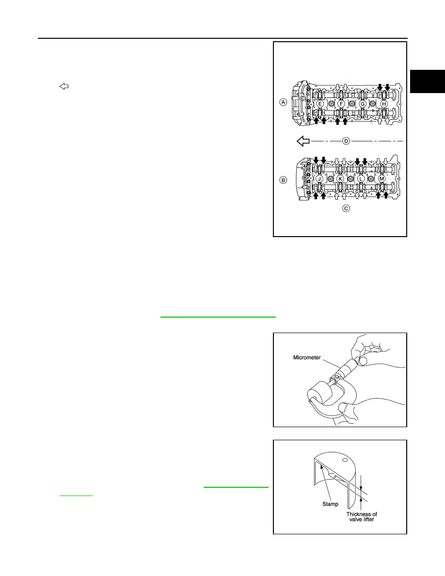
10. Turn the crankshaft pulley clockwise 90
° from the position of No.
3 cylinder compression TDC (clockwise by 360
° from the posi-
tion of No. 1 cylinder compression TDC) to measure the intake
and exhaust valve clearances of No. 6 cylinder (G) and the
exhaust valve clearance of No. 2 cylinder (E).
•
: Front
• A: RH
• B: LH
• C: Exhaust
• D: Intake
• E: No. 2 cylinder
• F: No. 4 cylinder
• G: No. 6 cylinder
• H: No. 8 cylinder
• J: No. 1 cylinder
• K: No. 3 cylinder
• L: No. 5 cylinder
• M: No. 7 cylinder
11. If out of specifications, adjust as necessary.
ADJUSTMENT
NOTE:
• Perform adjustment depending on the selected head thickness of the valve lifter.
• The specified valve lifter thickness is the dimension at normal temperatures. Ignore dimensional differences
caused by temperature. Use the specifications for hot engine condition to adjust.
1. Remove the camshaft. Refer to
EM-53, "Removal and Installation"
.
2. Remove the valve lifters at the locations that are out of specification.
3. Measure the center thickness of the removed valve lifters using
suitable tool.
4. Use the equation below to calculate the valve lifter thickness for
replacement.
• Valve lifter thickness calculation:
Thickness of replacement valve lifter = t1+ (C1 - C2)
t1 = Thickness of removed valve lifter
C1 = Measured valve clearance
C2= Standard valve clearance:
• Thickness of a new valve lifter can be identified by stamp
marks on the reverse side (inside the cylinder).
Stamp mark N788 indicates 7.88 mm (0.3102 in) in thickness.
• Available thickness of valve lifter: 25 sizes with range 7.88 to
8.36 mm (0.3102 to 0.3291 in) in steps of 0.02 mm (0.0008 in)
(when manufactured at factory). Refer to
5. Install the selected valve lifter.
WBIA0713E
KBIA0057E
KBIA0119E
Нет комментариевНе стесняйтесь поделиться с нами вашим ценным мнением.
Текст