Infiniti QX56 (JA60). Manual — part 242
BACK DOOR CLOSE SWITCH SYSTEM
DLK-139
< COMPONENT DIAGNOSIS >
[WITH INTELLIGENT KEY SYSTEM]
C
D
E
F
G
H
I
J
L
M
A
B
DLK
N
O
P
BACK DOOR CLOSE SWITCH SYSTEM
Diagnosis Procedure
INFOID:0000000005147007
Regarding Wiring Diagram information, refer to
DLK-199, "Wiring Diagram—AUTOMATIC BACK DOOR SYS-
1.
CLOSE SWITCH SIGNAL INSPECTION
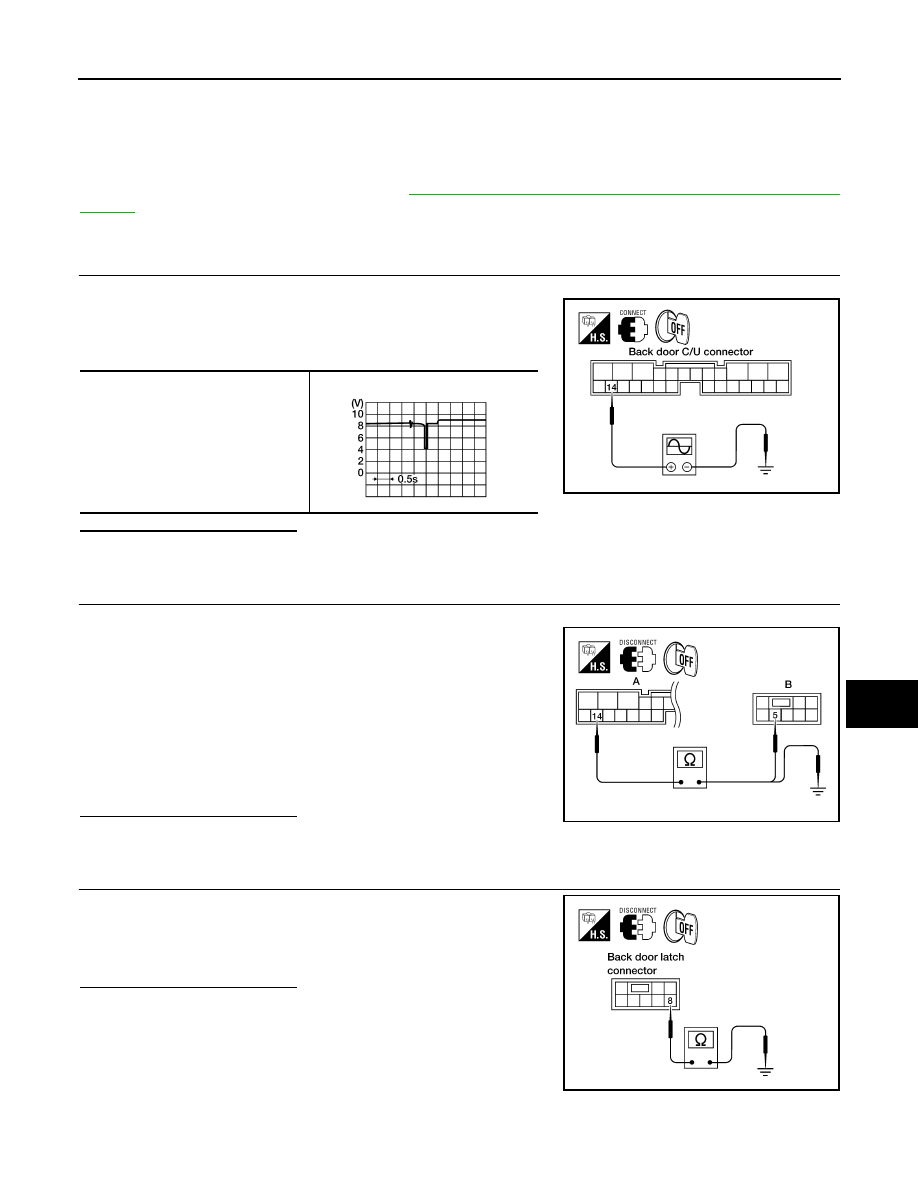
1. Turn ignition switch OFF.
2. While fully opening and closing the back door, check voltage
between back door control unit connector B55 terminal 14 and-
ground.
Is the inspection result normal?
YES
>> Close switch is OK.
NO
>> GO TO 2
2.
CLOSE SWITCH CIRCUIT INSPECTION
1. Disconnect back door latch and back door control unit connector.
2. Check continuity between back door control unit connector (A)
B55 terminal 14 and back door latch (close switch) connector
(B) D705 terminal 5.
3. Check continuity between back door control unit connector (A)
B55 terminal 14 and ground.
Is the inspection result normal?
YES
>> GO TO 3
NO
>> Repair the harness between the back door latch (close switch) and the back door control unit.
3.
CLOSE SWITCH GROUND INSPECTION
Check continuity between back door latch (close switch) connector
D705 terminal 8 and ground.
Is the inspection result normal?
YES
>> Replace the back door latch.
NO
>> Repair the harness between the back door latch (close
switch) and ground.
14 - Ground
LIIA0831E
WIIA1047E
14 - 5
: Continuity should exist.
14 - Ground
: Continuity should not exist.
ALKIA0677ZZ
8 - Ground
: Continuity should exist.
LIIA0828E
DLK-140
< COMPONENT DIAGNOSIS >
[WITH INTELLIGENT KEY SYSTEM]
BACK DOOR SWITCH
BACK DOOR SWITCH
Diagnosis Procedure
INFOID:0000000005147008
Regarding Wiring Diagram information, refer to
DLK-199, "Wiring Diagram—AUTOMATIC BACK DOOR SYS-
1.
BACK DOOR AND GLASS HATCH SWITCH SIGNAL INSPECTION
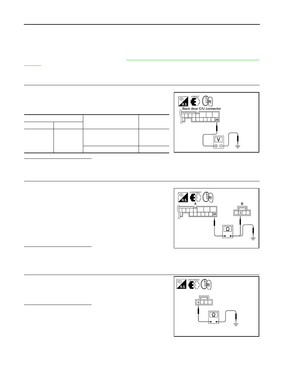
1. Turn ignition switch OFF.
2. While operating the back door and glass hatch switch assembly
(back door switch), check voltage between back door control
unit connector B55 terminal 26 and ground.
Is the inspection result normal?
YES
>> Switch is OK.
NO
>> GO TO 2
2.
BACK DOOR AND GLASS HATCH SWITCH CIRCUIT INSPECTION
1. Disconnect back door and glass hatch switch assembly (back door switch) and back door control unit.
2. Check continuity between back door control unit connector (A)
B55 terminal 26 and back door and glass hatch switch assembly
(back door switch) connector (B) D706 terminal 3.
3. Check continuity between back door control unit connector (A)
B55 terminal 26 and ground.
Is the inspection result normal?
YES
>> GO TO 3
NO
>> Repair the harness between the back door and glass hatch switch assembly (back door switch)
and the back door control unit.
3.
BACK DOOR AND GLASS HATCH SWITCH GROUND INSPECTION
Check continuity between back door and glass hatch switch assem-
bly (back door switch) connector D706 terminal 4 and ground.
Is the inspection result normal?
YES
>> Replace the back door and glass hatch switch assembly
(back door switch).
NO
>> Repair the harness between the back door and glass
hatch switch assembly (back door switch) and ground.
Terminal
Measuring condition
Voltage (V)
(Approx.)
(+)
(-)
26
Ground
Push the back door and glass
hatch switch assembly (back
door switch) (ON)
0
Other (OFF)
Battery voltage
LIIA0833E
26 - 3
: Continuity should exist.
26 - Ground
: Continuity should not exist.
ALKIA1791ZZ
4 - Ground
: Continuity should exist.
ALKIA1792ZZ
CINCH LATCH MOTOR SYSTEM
DLK-141
< COMPONENT DIAGNOSIS >
[WITH INTELLIGENT KEY SYSTEM]
C
D
E
F
G
H
I
J
L
M
A
B
DLK
N
O
P
CINCH LATCH MOTOR SYSTEM
Diagnosis Procedure
INFOID:0000000005147009
Regarding Wiring Diagram information, refer to
DLK-199, "Wiring Diagram—AUTOMATIC BACK DOOR SYS-
1.
CINCH LATCH MOTOR SIGNAL INSPECTION
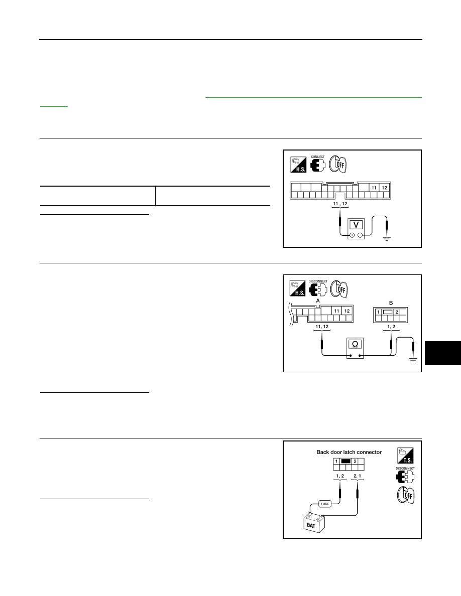
1. Turn ignition switch OFF.
2. While fully opening and closing the back door, check voltage
between back door control unit connector B55 terminals 11, 12
and ground.
Is the inspection result normal?
YES
>> GO TO 2
NO
>> Replace the back door control unit.
2.
CINCH LATCH MOTOR CIRCUIT INSPECTION
1. Disconnect back door latch and back door control unit connector.
2. Check continuity between back door control unit connector (A)
B55 terminals 11, 12 and back door latch (cinch latch motor)
connector D705 (B) terminals 1, 2.
3. Check continuity between back door control unit connector (A)
B55 terminals 11, 12 and ground.
Is the inspection result normal?
YES
>> GO TO 3
NO
>> Repair the harness between the back door latch (cinch latch motor) and the back door control
unit.
3.
CINCH LATCH MOTOR OPERATION INSPECTION
Connect battery power to terminals 1 and 2 on the back door latch
connector and check motor operation.
Is the inspection result normal?
YES
>> Motor is OK.
NO
>> Replace the back door latch.
11 - Ground
12 - Ground
Battery voltage
LIIA2397E
11 - 2
: Continuity should exist.
12 - 1
: Continuity should exist.
11 - Ground
: Continuity should not exist.
12 - Ground
: Continuity should not exist.
ALKIA0679ZZ
1 (+) - 2 (-)
: It operates.
1 (-) - 2 (+)
: It operates. (Reverse rotation)
LIIA0838E
DLK-142
< COMPONENT DIAGNOSIS >
[WITH INTELLIGENT KEY SYSTEM]
INTELLIGENT KEY UNIT POWER BACK DOOR INPUT SIGNAL
INTELLIGENT KEY UNIT POWER BACK DOOR INPUT SIGNAL
Description
INFOID:0000000005147010
Carrying the Intelligent Key, enables the driver to open the liftgate using the back door handle even when the
vehicle is locked. When lifting the handle, the back door handle switch sends this signal to the Intelligent Key
unit which treats it as a request switch signal. When the Intelligent Key unit, using the rear bumper antenna,
validates the presence of the Intelligent Key, it sends an open signal to the back door control unit regardless
whether the vehicle is locked.
Rear bumper antenna is mounted on the rear bumper and is used to allow the back door handle opening of
the locked back door when the Intelligent Key is present.
Diagnosis Procedure
INFOID:0000000005147011
Regarding Wiring Diagram information, refer to
DLK-199, "Wiring Diagram—AUTOMATIC BACK DOOR SYS-
1.
BACK DOOR HANDLE SWITCH SIGNAL INSPECTION
With all doors unlocked, check the back door handle operation by lifting the handle.
Did the back door respond correctly by opening?
YES
>> GO TO 2
NO
>> Refer to
DLK-140, "Diagnosis Procedure"
.
2.
KEYFOB SIGNAL INSPECTION
Check keyfob operation using lock and unlock buttons.
Did the keyfob respond correctly?
YES
>> GO TO 3
NO
>> Refer to
DLK-106, "Diagnosis Procedure"
.
3.
INTELLIGENT KEY UNIT SIGNAL INSPECTION
NOTE:
Since the diode is a uni-directional component, pay close attention to the polarity of the ohmmeter
being used as the presence of a diode in the circuit will affect the result.
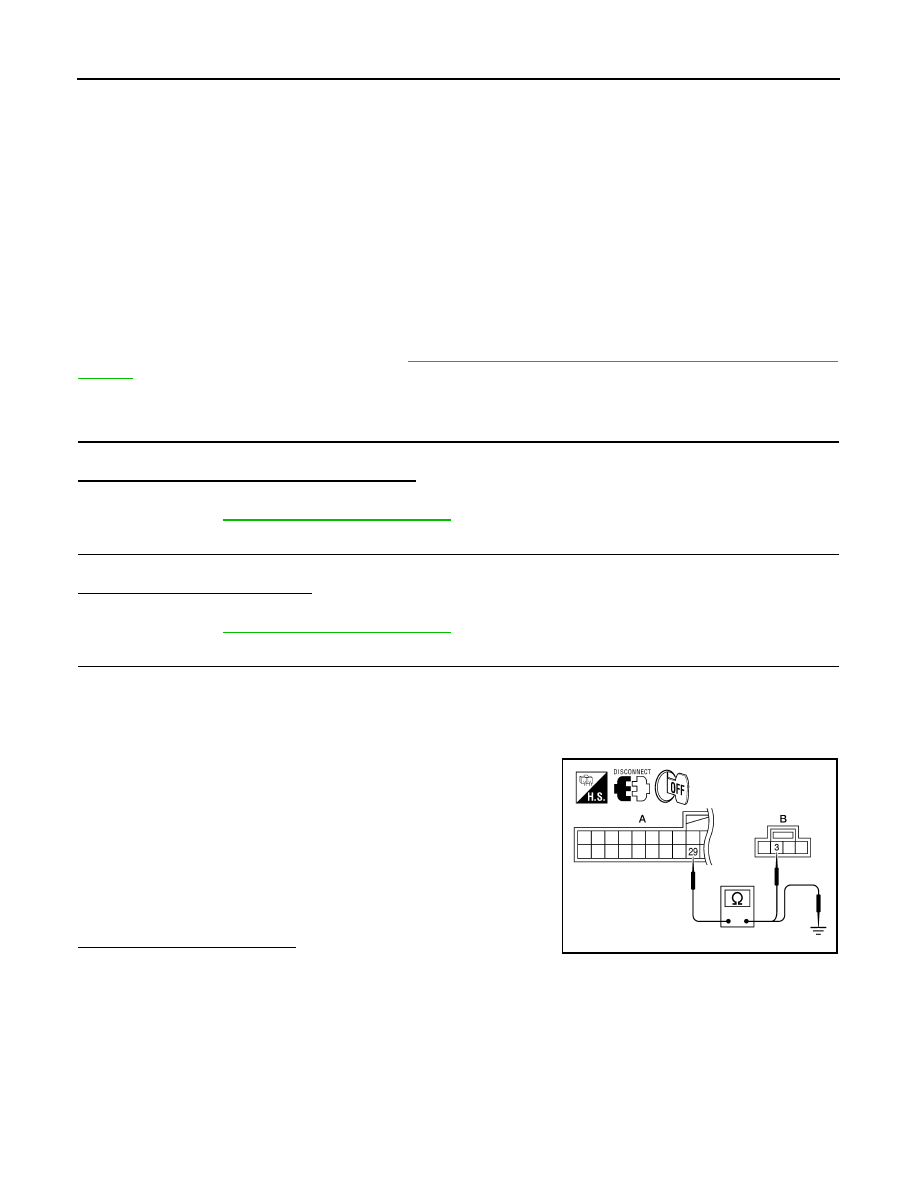
1. Turn ignition switch OFF.
2. Disconnect Intelligent Key unit, back door handle switch and back door control unit connectors.
3. Check continuity between Intelligent Key unit connector (A) M70
terminal 29 and back door handle switch connector (B) D706
terminal 3.
4. Check continuity between Intelligent Key unit connector (A) M70
terminal 29 and ground.
Is the inspection result normal?
YES
>> Replace the Intelligent Key unit.
NO
>> Repair or replace the harness or the diode as necessary.
29 (+) - 3 (-)
: Continuity should exist.
29 (+) - Ground (-) : Continuity should not exist.
ALKIA1793ZZ
Нет комментариевНе стесняйтесь поделиться с нами вашим ценным мнением.
Текст