Infiniti QX56 (JA60). Manual — part 243
INTELLIGENT KEY UNIT POWER BACK DOOR OUTPUT SIGNAL
DLK-143
< COMPONENT DIAGNOSIS >
[WITH INTELLIGENT KEY SYSTEM]
C
D
E
F
G
H
I
J
L
M
A
B
DLK
N
O
P
INTELLIGENT KEY UNIT POWER BACK DOOR OUTPUT SIGNAL
Description
INFOID:0000000005147012
The keyfob of the Intelligent Key unit is capable of opening and closing the power back door. The driver can
open or close the liftgate by pressing the liftgate button regardless whether the vehicle is locked provided the
keyfob is within operating range.
Diagnosis Procedure
INFOID:0000000005147013
Regarding Wiring Diagram information, refer to
DLK-199, "Wiring Diagram—AUTOMATIC BACK DOOR SYS-
1.
POWER LIFTGATE SWITCH FUNCTION INSPECTION
Check power liftgate switch using switch operation.
Did the back door respond correctly?
YES
>> GO TO 2
NO
>> Refer to
DLK-125, "Diagnosis Procedure"
2.
KEYFOB SIGNAL INSPECTION
Check keyfob operation using lock and unlock buttons.
Did the keyfob operate correctly?
YES
>> GO TO 3
NO
>> Refer to
DLK-106, "Diagnosis Procedure"
3.
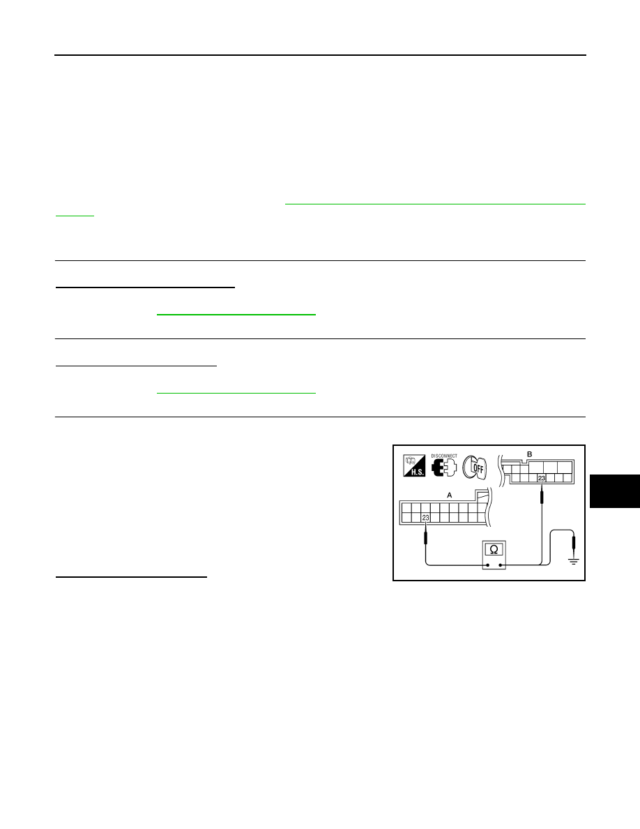
INTELLIGENT KEY UNIT SIGNAL INSPECTION
1. Turn ignition switch OFF.
2. Disconnect Intelligent Key unit, back door control unit and power liftgate switch connectors.
3. Check continuity between Intelligent Key unit connector (A) M70
terminal 23 and back door control unit connector (B) B55 termi-
nal 23.
4. Check continuity between Intelligent Key unit connector (A) M70
terminal 23 and ground.
Is the inspection result normal?
YES
>> Replace Intelligent Key unit.
NO
>> Repair or replace the harness as necessary.
23 - 23
: Continuity should exist.
23 - Ground
: Continuity should not exist.
ALKIA0680ZZ
DLK-144
< COMPONENT DIAGNOSIS >
[WITH INTELLIGENT KEY SYSTEM]
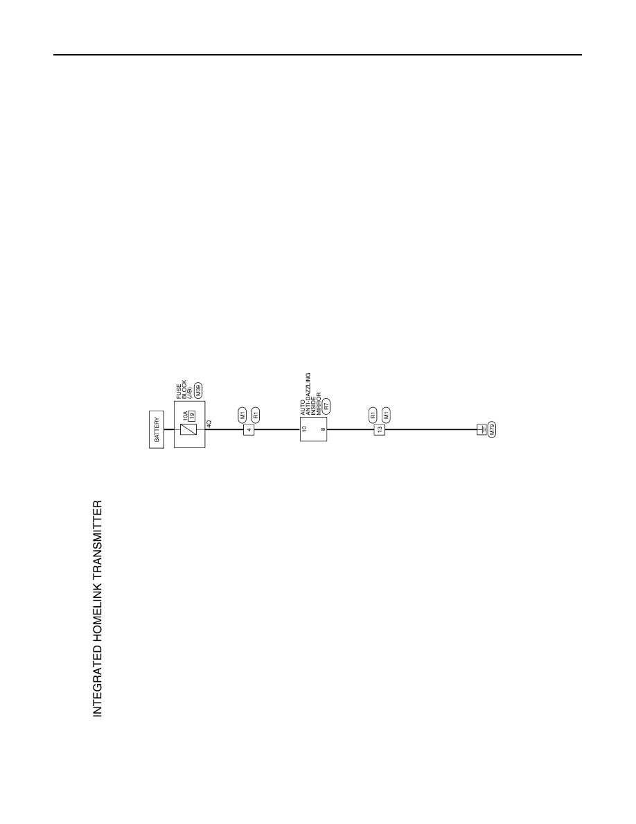
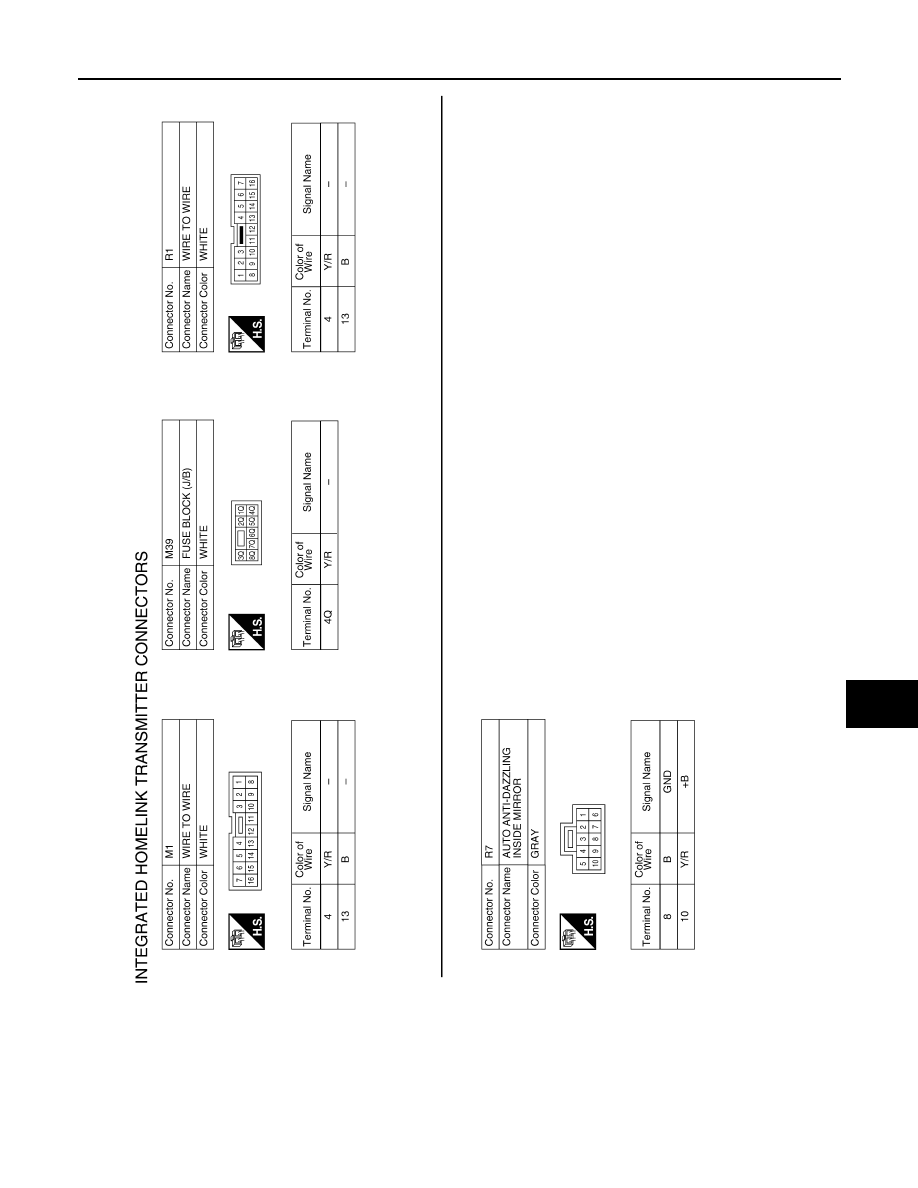
HOMELINK UNIVERSAL TRANSCEIVER
HOMELINK UNIVERSAL TRANSCEIVER
Wiring Diagram
INFOID:0000000005147014
ABKWA0018GB
HOMELINK UNIVERSAL TRANSCEIVER
DLK-145
< COMPONENT DIAGNOSIS >
[WITH INTELLIGENT KEY SYSTEM]
C
D
E
F
G
H
I
J
L
M
A
B
DLK
N
O
P
Description
INFOID:0000000005147015
Homelink universal transceiver can store and transmit a maximum of 3 radio signals.
Allows operation of garage doors, gates, home and office lighting, entry door locks and security system, etc.
Homelink universal transceiver power supply uses vehicle battery, which enables it to maintain every program
in case battery is discharged or removed.
ABKIA0056GB
DLK-146
< COMPONENT DIAGNOSIS >
[WITH INTELLIGENT KEY SYSTEM]
HOMELINK UNIVERSAL TRANSCEIVER
Component Function Check
INFOID:0000000005147016
1.
CHECK FUNCTION
Check that system receiver (garage door opener, etc.) operates with original hand-held transmitter.
Is the inspection result normal?
YES
>> GO TO 2
NO
>> Receiver or hand-held transmitter is malfunctioning.
2.
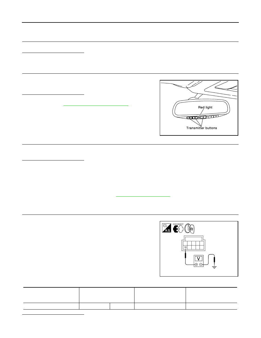
CHECK ILLUMINATION
1. Turn ignition switch “OFF”.
2. Press each of the transmitter buttons and watch for the red light
to illuminate with each button.
Is the inspection result normal?
YES
>> GO TO 3
NO
>> Refer to
DLK-146, "Diagnosis Procedure"
.
3.
CHECK TRANSMITTER
Check transmitter with Tool*.
*:For details, refer to Technical Service Bulletin.
Is the inspection result normal?
YES
>> Receiver or hand-held transmitter malfunction, not vehicle related.
NO
>> Replace auto anti-dazzling inside mirror (homelink universal transceiver).
Diagnosis Procedure
INFOID:0000000005147017
Regarding Wiring Diagram information, refer to
.
1.
CHECK POWER SUPPLY
1. Disconnect auto anti-dazzling inside mirror (homelink universal transceiver) connector.
2. Check voltage between auto anti-dazzling inside mirror
(homelink universal transceiver) harness connector and ground.
Is the inspection result normal?
YES
>> GO TO 2
PIIA4815E
ALKIA0659ZZ
Auto anti-dazzling inside mirror
(Homelink universal transceiver)
connector
Terminal Condition
Voltage (V)
(Approx.)
R7
10
Ground
Ignition switch position: LOCK
Battery voltage
Нет комментариевНе стесняйтесь поделиться с нами вашим ценным мнением.
Текст