Infiniti QX56 (JA60). Manual — part 277
P1810 NEUTRAL-4LO SWITCH
DLN-31
< COMPONENT DIAGNOSIS >
[ATX14B]
C
E
F
G
H
I
J
K
L
M
A
B
DLN
N
O
P
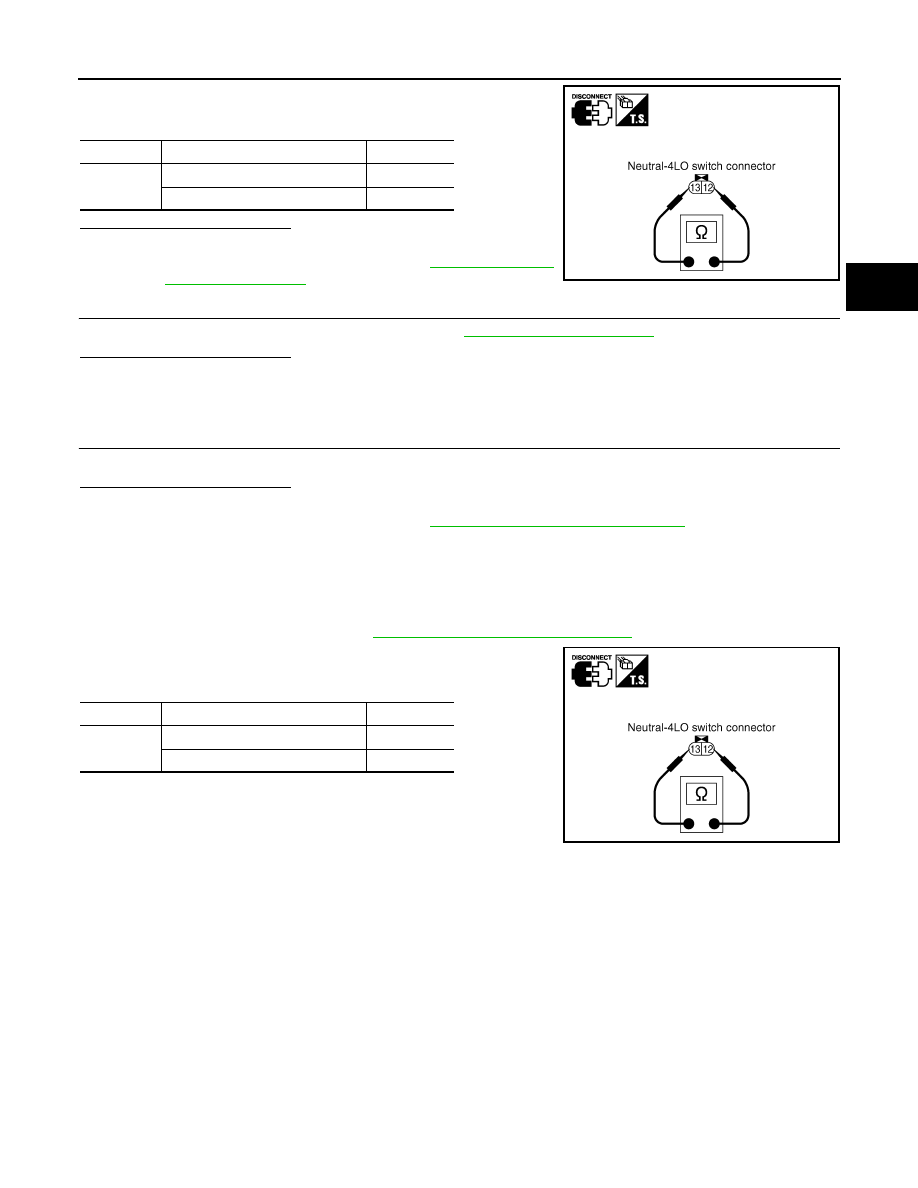
4. Push and release neutral-4LO switch and check continuity
between neutral-4LO switch terminals 12 and 13.
Are inspection results normal?
YES
>> GO TO 5.
NO
>> Replace neutral-4LO switch. Refer to
5.
CHECK TRANSFER CONTROL UNIT
Check transfer control unit input/output signal. Refer to
Are inspection results normal?
YES
>> GO TO 6.
NO
>> Check transfer control unit pin terminals for damage or loose connection with harness connector.
If any items are damaged, repair or replace damaged parts.
6.
CHECK DTC
Drive the vehicle and then perform self-diagnosis.
Are inspection results normal?
YES
>> Inspection End.
NO
>> Replace transfer control unit. Refer to
DLN-130, "Removal and Installation"
Component Inspection
INFOID:0000000005148791
1. Turn ignition switch OFF. (Stay for at least 5 seconds.)
2. Disconnect neutral-4LO switch harness connector.
3. Remove neutral-4LO switch. Refer to
DLN-16, "Component Parts Location"
.
4. Push and release neutral-4LO switch and check continuity
between neutral-4LO switch terminals 12 and 13.
5. If the inspection results are abnormal replace the neutral-4LO
switch.
Terminal
Condition
Continuity
12 - 13
Push neutral-4LO switch
Yes
Release neutral-4LO switch
No
SDIA2696E
Terminal
Condition
Continuity
12 - 13
Push neutral-4LO switch
Yes
Release neutral-4LO switch
No
SDIA2696E
DLN-32
< COMPONENT DIAGNOSIS >
[ATX14B]
P1813 4WD SHIFT SWITCH
P1813 4WD SHIFT SWITCH
Description
INFOID:0000000005148792
The 4WD shift switch allows the driver to select AUTO, 2WD or 4WD and 4H or 4LO. DTC P1813 will set if
more than two switch inputs are simultaneously detected by the transfer control unit due to a short circuit in the
4WD shift switch.
DTC Logic
INFOID:0000000005148793
DTC DETECTION LOGIC
DTC CONFIRMATION PROCEDURE
1.
DTC CONFIRMATION PROCEDURE
1. Turn ignition switch ON.
2. Perform self-diagnosis.
Is DTC P1813 displayed?
YES
>> Perform diagnosis procedure. Refer to
.
NO
>> Inspection End.
Diagnosis Procedure
INFOID:0000000005148794
Regarding Wiring Diagram information, refer to
DLN-89, "Wiring Diagram - ALL-MODE 4WD SYSTEM -"
.
1.
CHECK 4WD SHIFT SWITCH SIGNAL
With CONSULT-III
1. Turn ignition switch ON. (Do not start engine.)
2. Select DATA MONITOR mode for ALL MODE AWD/4WD with CONSULT-III.
3. Read out ON/OFF switching action of the 2WD SWITCH, AUTO SWITCH, LOCK SWITCH, 4L SW with
operating 4WD shift switch.
Without CONSULT-III
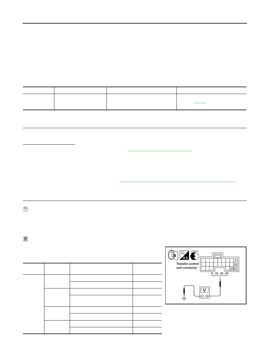
1. Turn ignition switch ON. (Do not start engine.)
2. Check voltage between transfer control unit harness connector
terminals and ground.
DTC
CONSULT-III
Diagnostic item is detected when...
Reference
[P1813]
4WD MODE SW
More than two switch inputs are simulta-
neously detected due to short circuit of
4WD shift switch.
Refer to
.
Connector
Terminal
Condition
Voltage (Ap-
prox.)
E142
9 - ground
4WD shift switch: 2WD
Battery voltage
4WD shift switch: AUTO, 4H or 4LO 0V
18 - ground
4WD shift switch: 4H
Battery voltage
4WD shift switch: 2WD, AUTO or
4LO
0V
23 - ground
4WD shift switch: 4LO
Battery voltage
4WD shift switch: 2WD, AUTO or 4H 0V
24 - ground
4WD shift switch: AUTO
Battery voltage
4WD shift switch: 2WD, 4H or 4LO
0V
WDIA0148E
P1813 4WD SHIFT SWITCH
DLN-33
< COMPONENT DIAGNOSIS >
[ATX14B]
C
E
F
G
H
I
J
K
L
M
A
B
DLN
N
O
P
Are inspection results normal?
YES
>> GO TO 5.
NO
>> GO TO 2.
2.
CHECK 4WD SHIFT SWITCH POWER SUPPLY CIRCUIT
1. Turn ignition switch OFF. (Stay for at least 5 seconds.)
2. Disconnect 4WD shift switch harness connector.
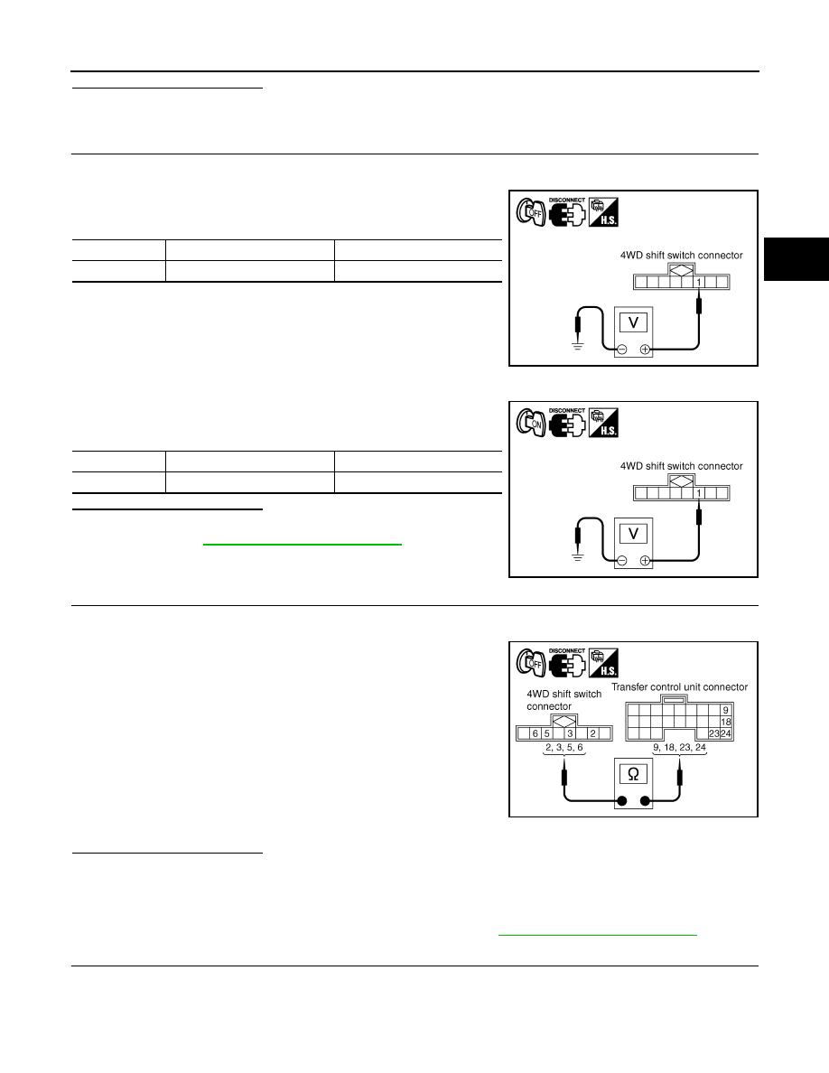
3. Check voltage between 4WD shift switch harness connector ter-
minal 1 and ground.
4. Turn ignition switch ON. (Do not start engine.)
5. Check voltage between 4WD shift switch harness connector ter-
minal 1 and ground.
Are inspection results normal?
YES
>> GO TO 3.
NO
>> Refer to
.
3.
CHECK HARNESS BETWEEN 4WD SHIFT SWITCH AND TRANSFER CONTROL UNIT
1. Turn ignition switch OFF. (Stay for at least 5 seconds.)
2. Disconnect transfer control unit harness connector and the 4WD shift switch harness connector.
3. Check continuity between the following terminals.
-
Transfer control unit harness connector E142 terminal 9 and
4WD shift switch harness connector M141 terminal 2.
-
Transfer control unit harness connector E142 terminal 18 and
4WD shift switch harness connector M141 terminal 5.
-
Transfer control unit harness connector E142 terminal 23 and
4WD shift switch harness connector M141 terminal 6.
-
Transfer control unit harness connector E142 terminal 24 and
4WD shift switch harness connector M141 terminal 3.
Also check harness for short to ground and short to power.
Are inspection results normal?
YES
>> GO TO 4.
NO
>> Check the following. If any items are damaged, repair or replace damaged parts.
• Harness for short or open between battery and transfer shut off relay harness connector E69
terminal 5.
• Power supply circuit for transfer control unit. Refer to
.
4.
CHECK 4WD SHIFT SWITCH
1. Turn ignition switch OFF. (Stay for at least 5 seconds.)
2. Disconnect 4WD shift switch harness connector.
Connector Terminal
Voltage
(Approx.)
M141
1 - Ground
0V
SDIA2383E
Connector
Terminal
Voltage (Approx.)
M141
1 - Ground
Battery voltage
PDIA0210E
Continuity should exist.
SDIA2699E
DLN-34
< COMPONENT DIAGNOSIS >
[ATX14B]
P1813 4WD SHIFT SWITCH
3. Operate 4WD shift switch and check continuity between 4WD
shift switch terminals.
Are inspection results normal?
YES
>> GO TO 5.
NO
>> Replace 4WD shift switch.
5.
CHECK TRANSFER CONTROL UNIT
Check transfer control unit input/output signal. Refer to
Are inspection results normal?
YES
>> GO TO 6.
NO
>> Check transfer control unit pin terminals for damage or loose connection with harness connector.
If any items are damaged, repair or replace damaged parts.
6.
CHECK DTC
Drive the vehicle and then perform self-diagnosis.
Are inspection results normal?
YES
>> Inspection End.
NO
>> Replace transfer control unit. Refer to
DLN-130, "Removal and Installation"
.
Component Inspection
INFOID:0000000005148795
COMPONENT INSPECTION
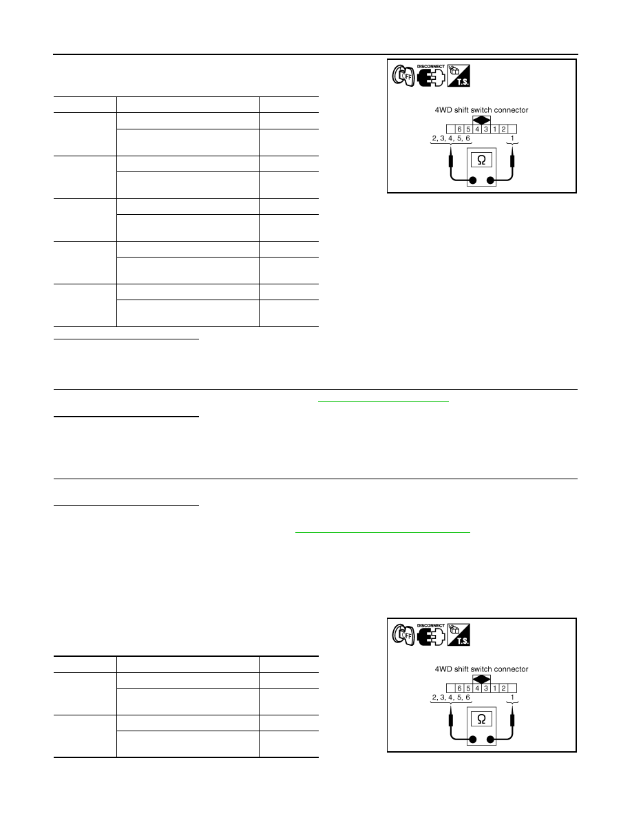
1. Turn ignition switch OFF. (Stay for at least 5 second.)
2. Disconnect 4WD shift switch harness connector.
3. Operate 4WD shift switch and check continuity between 4WD
shift switch terminals.
Terminal
Condition
Continuity
1 - 2
4WD shift switch: 2WD
Yes
4WD shift switch: AUTO, 4H and
4LO
No
1 - 3
4WD shift switch: AUTO
Yes
4WD shift switch: 2WD, 4H and
4LO
No
1 - 4
4WD shift switch: 2WD
No
4WD shift switch: AUTO, 4H and
4LO
Yes
1 - 5
4WD shift switch: 4H
Yes
4WD shift switch: 2WD, AUTO,
and 4LO
No
1 - 6
4WD shift switch: 4LO
Yes
4WD shift switch: 2WD, AUTO and
4H
No
WDIA0205E
Terminal
Condition
Continuity
1 - 2
4WD shift switch: 2WD
Yes
4WD shift switch: AUTO, 4H and
4LO
No
1 - 3
4WD shift switch: AUTO
Yes
4WD shift switch: 2WD, 4H and
4LO
No
WDIA0205E
Нет комментариевНе стесняйтесь поделиться с нами вашим ценным мнением.
Текст