Infiniti QX56 (JA60). Manual — part 368
EC-124
< COMPONENT DIAGNOSIS >
[VK56DE]
P0117, P0118 ECT SENSOR
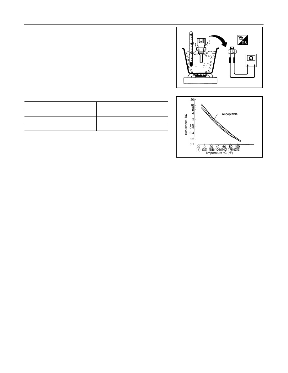
1. Check resistance between engine coolant temperature sensor
terminals 1 and 2 as shown in the figure.
2. If NG, replace engine coolant temperature sensor.
PBIB2005E
Engine coolant temperature
°C (°F)]
Resistance (k
Ω)
20 (68)
2.1 - 2.9
50 (122)
0.68 - 1.00
90 (194)
0.236 - 0.260
SEF012P
P0122, P0123 TP SENSOR
EC-125
< COMPONENT DIAGNOSIS >
[VK56DE]
C
D
E
F
G
H
I
J
K
L
M
A
EC
N
P
O
P0122, P0123 TP SENSOR
Component Description
INFOID:0000000005149136
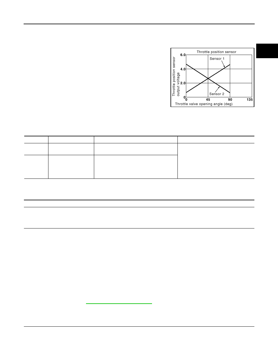
Electric throttle control actuator consists of throttle control motor,
throttle position sensor, etc. The throttle position sensor responds to
the throttle valve movement.
The throttle position sensor has the two sensors. These sensors are
a kind of potentiometers which transform the throttle valve position
into output voltage, and emit the voltage signal to the ECM. In addi-
tion, these sensors detect the opening and closing speed of the
throttle valve and feed the voltage signals to the ECM. The ECM
judges the current opening angle of the throttle valve from these sig-
nals and the ECM controls the throttle control motor to make the
throttle valve opening angle properly in response to driving condi-
tion.
On Board Diagnosis Logic
INFOID:0000000005149137
These self-diagnoses have the one trip detection logic.
FAIL-SAFE MODE
When the malfunction is detected, ECM enters fail-safe mode and the MIL lights up.
DTC Confirmation Procedure
INFOID:0000000005149138
NOTE:
If DTC Confirmation Procedure has been previously conducted, always perform the following procedure
before conducting the next step.
1. Turn ignition switch OFF and wait at least 10 seconds.
2. Turn ignition switch ON.
3. Turn ignition switch OFF and wait at least 10 seconds.
TESTING CONDITION:
Before performing the following procedure, confirm that battery voltage is more than 8V at idle.
1. Start engine and let it idle for 1 second.
2. Check DTC.
3. If DTC is detected, go to
.
Diagnosis Procedure
INFOID:0000000005149139
1.
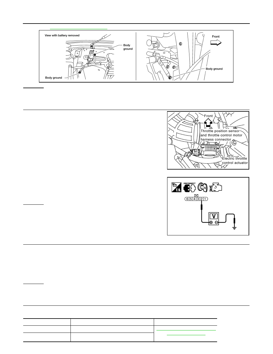
CHECK GROUND CONNECTIONS
1. Turn ignition switch OFF.
2. Loosen and retighten three ground screws on the body.
PBIB0145E
DTC No.
Trouble diagnosis name
DTC detecting condition
Possible cause
P0122
0122
Throttle position sensor
2 circuit low input
An excessively low voltage from the TP sensor
2 is sent to ECM.
• Harness or connectors
(TP sensor 2 circuit is open or shorted.)
(APP sensor 2 circuit is shorted.)
• Electric throttle control actuator
(TP sensor 2)
• Accelerator pedal position sensor
(APP sensor 2)
P0123
0123
Throttle position sensor
2 circuit high input
An excessively high voltage from the TP sensor
2 is sent to ECM.
Engine operation condition in fail-safe mode
The ECM controls the electric throttle control actuator in regulating the throttle opening in order for the idle position to be within +10
degrees.
The ECM regulates the opening speed of the throttle valve to be slower than the normal condition.
So, the acceleration will be poor.
EC-126
< COMPONENT DIAGNOSIS >
[VK56DE]
P0122, P0123 TP SENSOR
OK or NG
OK
>> GO TO 2.
NG
>> Repair or replace ground connections.
2.
CHECK THROTTLE POSITION SENSOR 2 POWER SUPPLY CIRCUIT-I
1. Disconnect electric throttle control actuator harness connector.
2. Turn ignition switch ON.
3. Check voltage between electric throttle control actuator terminal
2 and ground with CONSULT-III or tester.
OK or NG
OK
>> GO TO 7.
NG
>> GO TO 3.
3.
CHECK THROTTLE POSITION SENSOR 2 POWER SUPPLY CIRCUIT-II
1. Turn ignition switch OFF.
2. Disconnect ECM harness connector.
3. Check harness continuity between electric throttle control actuator terminal 2 and ECM terminal 47.
Refer to Wiring Diagram.
OK or NG
OK
>> GO TO 4.
NG
>> Repair or replace open circuit.
4.
CHECK THROTTLE POSITION SENSOR 2 POWER SUPPLY CIRCUIT-III
Check harness for short to power and short to ground, between the following terminals.
BBIA0354E
PBIB1480E
Voltage: Approximately 5 V
PBIB2065E
Continuity should exist.
ECM terminal
Sensor terminal
Reference Wiring Diagram
47
Electric throttle control actuator terminal 2
EC-435, "Wiring Diagram - ENGINE
91
APP sensor terminal 6

P0122, P0123 TP SENSOR
EC-127
< COMPONENT DIAGNOSIS >
[VK56DE]
C
D
E
F
G
H
I
J
K
L
M
A
EC
N
P
O
OK or NG
OK
>> GO TO 5.
NG
>> Repair short to ground or short to power in harness or connectors.
5.
CHECK ACCELERATOR PEDAL POSITION SENSOR
EC-381, "Component Inspection"
OK or NG
OK
>> GO TO 11.
NG
>> GO TO 6.
6.
REPLACE ACCELERATOR PEDAL ASSEMBLY
1. Replace the accelerator pedal assembly.
2. Perform
EC-18, "Accelerator Pedal Released Position Learning"
3. Perform
EC-18, "Throttle Valve Closed Position Learning"
.
4. Perform
EC-18, "Idle Air Volume Learning"
>> INSPECTION END
7.
CHECK THROTTLE POSITION SENSOR 2 GROUND CIRCUIT FOR OPEN AND SHORT
1. Turn ignition switch OFF.
2. Disconnect ECM harness connector.
3. Check harness continuity between electric throttle control actuator terminal 4 and ECM terminal 66.
Refer to Wiring Diagram.
4. Also check harness for short to ground and short to power.
OK or NG
OK
>> GO TO 8.
NG
>> Repair open circuit or short to ground or short to power in harness or connectors.
8.
CHECK THROTTLE POSITION SENSOR 2 INPUT SIGNAL CIRCUIT FOR OPEN AND SHORT
1. Check harness continuity between ECM terminal 69 and electric throttle control actuator terminal 3.
Refer to Wiring Diagram.
2. Also check harness for short to ground and short to power.
OK or NG
OK
>> GO TO 9.
NG
>> Repair open circuit or short to ground or short to power in harness or connectors.
9.
CHECK THROTTLE POSITION SENSOR
EC-128, "Component Inspection"
OK or NG
OK
>> GO TO 11.
NG
>> GO TO 10.
10.
REPLACE ELECTRIC THROTTLE CONTROL ACTUATOR
1. Replace the electric throttle control actuator.
2. Perform
EC-18, "Throttle Valve Closed Position Learning"
.
3. Perform
EC-18, "Idle Air Volume Learning"
>> INSPECTION END
11.
CHECK INTERMITTENT INCIDENT
GI-35, "How to Check Terminal"
GI-38, "Intermittent Incident"
Continuity should exist.
Continuity should exist.
Нет комментариевНе стесняйтесь поделиться с нами вашим ценным мнением.
Текст