Infiniti QX56 (JA60). Manual — part 544
DRIVE SHAFT
FAX-15
< DISASSEMBLY AND ASSEMBLY >
C
E
F
G
H
I
J
K
L
M
A
B
FAX
N
O
P
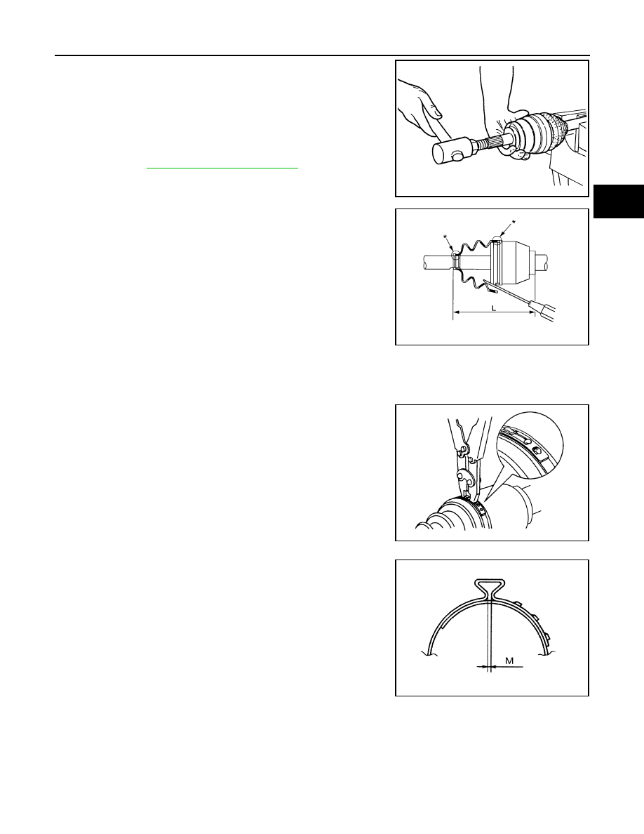
4. Attach the circlip to the drive shaftm making sure circlip fits
securely into groove on drive shaft. Then install drive shaft nut to
end of joint sub-assembly, and press-fit the circlip using a suit-
able tool as shown.
NOTE:
Discard the old circlip and use a new one for assembly.
5. Insert the specified quantity of Genuine NISSAN Grease or
equivalent, into the joint sub-assembly and the large end of the
MA-13, "Fluids and Lubricants"
6. Install the boot securely into the grooves (indicated by the *
marks) as shown.
CAUTION:
If there is grease on the boot mounting surfaces (indicated
by the * marks) of the drive shaft and joint sub-assembly,
the boot may come off. Remove all grease from the drive
shaft surfaces.
7. Check that the boot installation length (L) is the specified length.
Insert a suitable tool into the large end of the boot, as shown.
Bleed the air from the boot to prevent boot deformation.
CAUTION:
• The boot may break if the boot installation length is less than the specified length.
• Do not contact inside surface of boot with the tip of the suitable tool.
8. Secure large and small ends of the boot using new boot bands
using tool as shown.
NOTE:
Discard the old boot bands and use new ones for assembly.
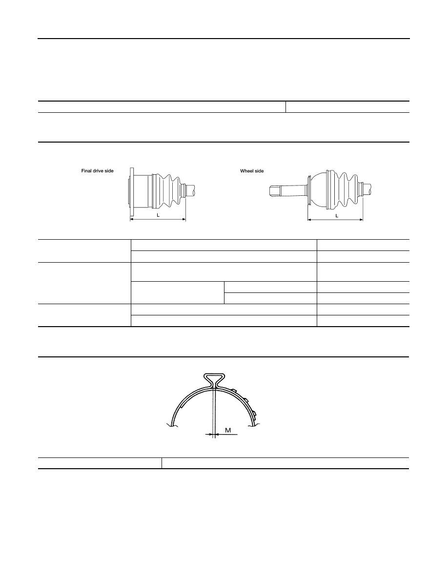
• Secure boot band so that dimension (M) meets specification
as shown.
9. After installing the housing to the shaft, rotate the boot to check that it is positioned correctly. If the boot is
not positioned correctly, remove the old boot bands then reposition the boot and secure the boot with new
boot bands.
Grease capacity
: 145
− 165 g (5.11 − 5.82 oz)
RAC0049D
Boot installation length (L)
: 168.4 mm (6.63 in)
Tool number : KV40107300 ( — )
WDIA0288E
RAC1133D
Dimension (M)
: 1.0 – 4.0 mm (0.039 – 0.157 in)
DSF0047D
FAX-16
< SERVICE DATA AND SPECIFICATIONS (SDS)
SERVICE DATA AND SPECIFICATIONS (SDS)
SERVICE DATA AND SPECIFICATIONS (SDS)
SERVICE DATA AND SPECIFICATIONS (SDS)
Wheel Bearing
INFOID:0000000005148947
Drive Shaft
INFOID:0000000005148948
Boot Bands
INFOID:0000000005148949
Unit: mm (in)
Wheel bearing axial end play
0.05 mm (0.002 in) or less
Drive shaft joint type
Final drive side
Rzeppa
Wheel side
Rzeppa
Grease
Quality
Nissan Genuine Grease or
equivalent
Capacity
Final drive side
130 - 150 g (4.58 - 5.29 oz)
Wheel side
145 - 165 g (5.11 - 5.82 oz)
Boot length
Final drive side (L)
145 mm (5.71 in)
Wheel side (L)
168.4 mm (6.63 in)
WDIA0055E
Dimension (M)
1.0 - 4.0 (0.039 - 0.157)
DSF0047D
FL-1
ENGINE
C
D
E
F
G
H
I
J
K
L
M
SECTION
FL
A
FL
N
O
P
CONTENTS
FUEL SYSTEM
PRECAUTION . . . . . . . . . . . ...
PRECAUTIONS . . . . . . . . . . . . ...
Precaution Necessary for Steering Wheel Rota-
tion After Battery Disconnect . . . . . . . . .....
FUEL SYSTEM . . . . . . . . . . . . .
General Precaution . . . . . . . . . . . . ...
PREPARATION . . . . . . . . . . .
PREPARATION . . . . . . . . . . . . ...
Special Service Tool . . . . . . . . . . . .....
Commercial Service Tool . . . . . . . . . . ..
BASIC INSPECTION . . . . . . . . .
FUEL SYSTEM . . . . . . . . . . . . .
Checking Fuel Line . . . . . . . . . . . . ...
REMOVAL AND INSTALLATION . . . .
FUEL LEVEL SENSOR UNIT, FUEL FILTER
AND FUEL PUMP ASSEMBLY . . . . . . .
Removal and Installation . . . . . . . . . . ..
FUEL TANK . . . . . . . . . . . . . ..
Removal and Installation . . . . . . . . . . .
DISASSEMBLY AND ASSEMBLY . . . ..
FUEL LEVEL SENSOR UNIT, FUEL FILTER
AND FUEL PUMP ASSEMBLY . . . . . .
Disassembly and Assembly . . . . . . . . . .
SERVICE DATA AND SPECIFICATIONS
(SDS) . . . . . . . . . . . . . . .
SERVICE DATA AND SPECIFICATIONS
(SDS) . . . . . . . . . . . . . . . . .
FL-2
< PRECAUTION >
PRECAUTIONS
PRECAUTION
PRECAUTIONS
Precaution for Supplemental Restraint System (SRS) "AIR BAG" and "SEAT BELT
PRE-TENSIONER"
INFOID:0000000005390742
The Supplemental Restraint System such as “AIR BAG” and “SEAT BELT PRE-TENSIONER”, used along
with a front seat belt, helps to reduce the risk or severity of injury to the driver and front passenger for certain
types of collision. This system includes seat belt switch inputs and dual stage front air bag modules. The SRS
system uses the seat belt switches to determine the front air bag deployment, and may only deploy one front
air bag, depending on the severity of a collision and whether the front occupants are belted or unbelted.
Information necessary to service the system safely is included in the SR and SB section of this Service Man-
ual.
WARNING:
• To avoid rendering the SRS inoperative, which could increase the risk of personal injury or death in
the event of a collision which would result in air bag inflation, all maintenance must be performed by
an authorized NISSAN/INFINITI dealer.
• Improper maintenance, including incorrect removal and installation of the SRS, can lead to personal
injury caused by unintentional activation of the system. For removal of Spiral Cable and Air Bag
Module, see the SR section.
• Do not use electrical test equipment on any circuit related to the SRS unless instructed to in this
Service Manual. SRS wiring harnesses can be identified by yellow and/or orange harnesses or har-
ness connectors.
PRECAUTIONS WHEN USING POWER TOOLS (AIR OR ELECTRIC) AND HAMMERS
WARNING:
• When working near the Airbag Diagnosis Sensor Unit or other Airbag System sensors with the Igni-
tion ON or engine running, DO NOT use air or electric power tools or strike near the sensor(s) with a
hammer. Heavy vibration could activate the sensor(s) and deploy the air bag(s), possibly causing
serious injury.
• When using air or electric power tools or hammers, always switch the Ignition OFF, disconnect the
battery, and wait at least 3 minutes before performing any service.
Precaution Necessary for Steering Wheel Rotation After Battery Disconnect
INFOID:0000000005390743
NOTE:
• This Procedure is applied only to models with Intelligent Key system and NATS (NISSAN ANTI-THEFT SYS-
TEM).
• Remove and install all control units after disconnecting both battery cables with the ignition knob in the
″LOCK″ position.
• Always use CONSULT-III to perform self-diagnosis as a part of each function inspection after finishing work.
If DTC is detected, perform trouble diagnosis according to self-diagnostic results.
For models equipped with the Intelligent Key system and NATS, an electrically controlled steering lock mech-
anism is adopted on the key cylinder.
For this reason, if the battery is disconnected or if the battery is discharged, the steering wheel will lock and
steering wheel rotation will become impossible.
If steering wheel rotation is required when battery power is interrupted, follow the procedure below before
starting the repair operation.
OPERATION PROCEDURE
1. Connect both battery cables.
NOTE:
Supply power using jumper cables if battery is discharged.
2. Use the Intelligent Key or mechanical key to turn the ignition switch to the
″ACC″ position. At this time, the
steering lock will be released.
3. Disconnect both battery cables. The steering lock will remain released and the steering wheel can be
rotated.
4. Perform the necessary repair operation.
Нет комментариевНе стесняйтесь поделиться с нами вашим ценным мнением.
Текст