Infiniti QX56 (JA60). Manual — part 622
INL-16
< COMPONENT DIAGNOSIS >
POWER SUPPLY AND GROUND CIRCUIT
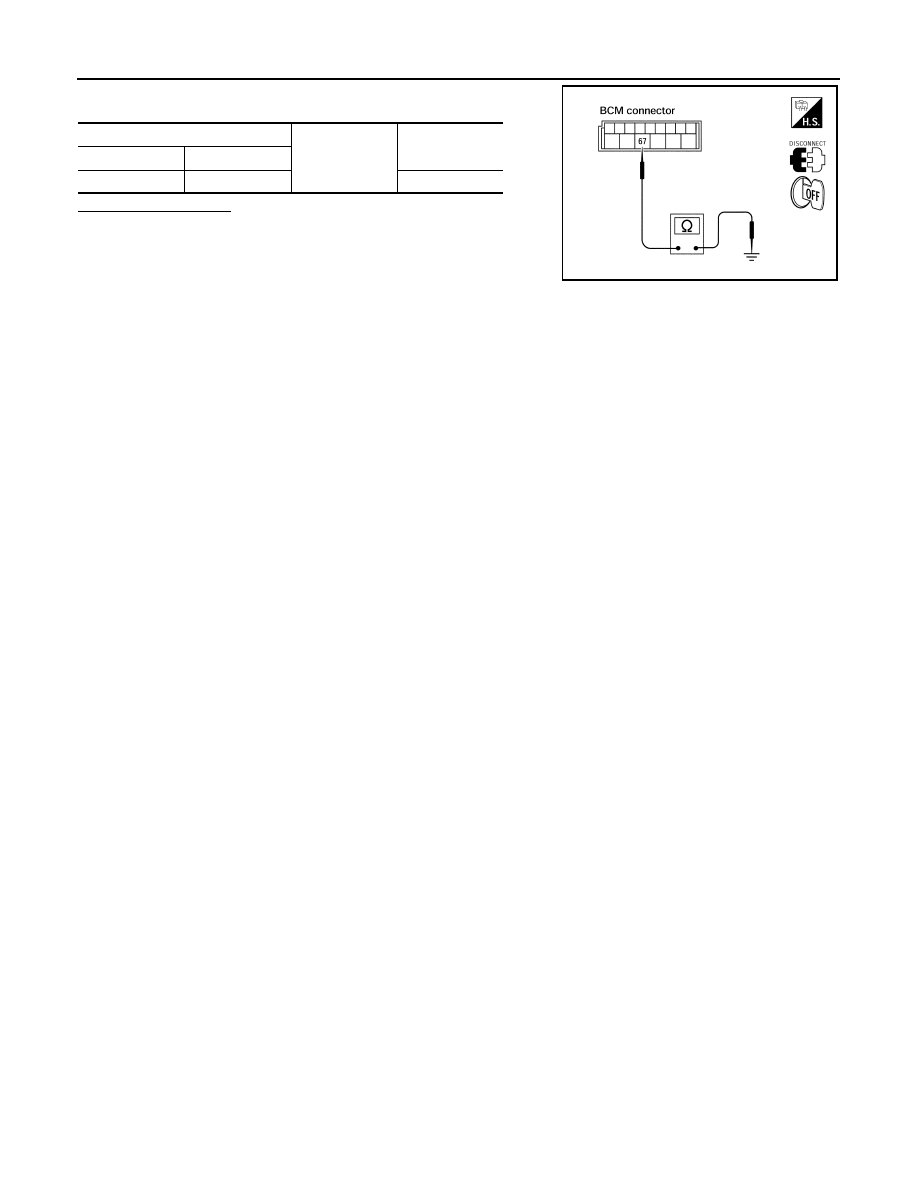
Check continuity between BCM harness connector and ground.
Does continuity exist?
YES
>> Inspection End.
NO
>> Repair or replace harness.
BCM
Ground
Continuity
Connector
Terminal
M20
67
Yes
LIIA0915E
BATTERY SAVER OUTPUT/POWER SUPPLY CIRCUIT
INL-17
< COMPONENT DIAGNOSIS >
C
D
E
F
G
H
I
J
K
M
A
B
INL
N
O
P
BATTERY SAVER OUTPUT/POWER SUPPLY CIRCUIT
Description
INFOID:0000000005146727
Provides the battery saver output/power supply. Also cuts the power supply when the interior room lamp bat-
tery saver is activating.
Component Function Check
INFOID:0000000005146728
1.
CHECK BATTERY SAVER OUTPUT/POWER SUPPLY FUNCTION
CONSULT-III
1. Turn ignition switch ON.
2. Turn each interior room lamp ON.
-
Front room/map lamp assembly
-
Vanity lamps
-
Personal lamp 2nd row
-
Personal lamp 3rd row
-
Cargo lamp
3. Open the driver door to turn ON the step lamps, foot lamps and puddle lamps.
-
Front step lamps
-
Rear step lamps
-
Foot lamps
-
Puddle lamps
-
Ignition keyhole Illumination
4. Select “BATTERY SAVER” of BCM (BATTERY SAVER) active test item.
5. While operating the test item, check that each interior room lamp turns ON/OFF.
Is the inspection result normal?
YES
>> Battery saver output/power supply circuit is normal.
NO
>> Refer to
.
Diagnosis Procedure
INFOID:0000000005146729
Regarding Wiring Diagram information, refer to
.
1.
CHECK BATTERY SAVER OUTPUT/POWER SUPPLY OUTPUT
CONSULT-III
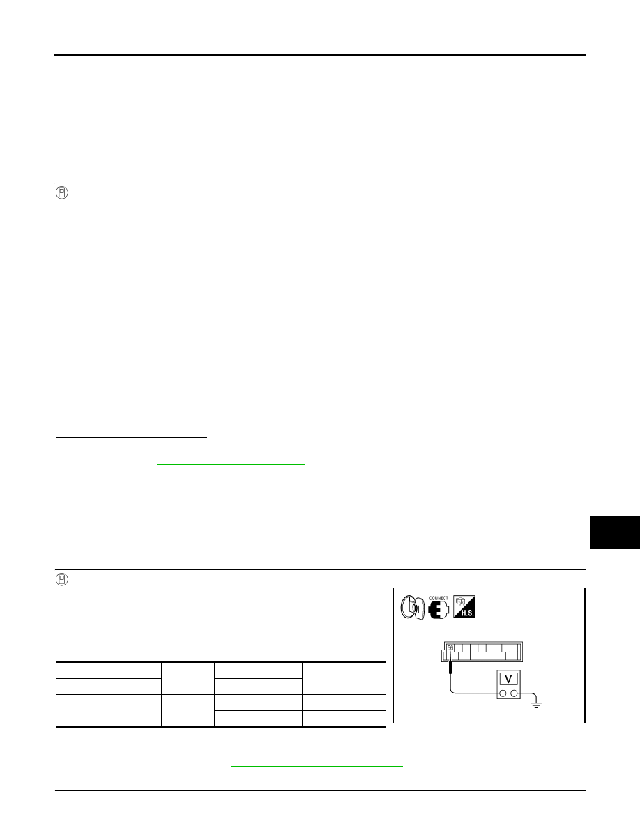
1. Turn ignition switch ON.
2. Select “BATTERY SAVER” of BCM (BATTERY SAVER) active
test item.
3. While operating the test item, check voltage between BCM con-
nector M20 terminal 56 and ground.
Is the inspection result normal?
YES
>> GO TO 2
NO
>> Replace BCM. Refer to
BCS-59, "Removal and Installation"
2.
CHECK BATTERY SAVER OUTPUT/POWER SUPPLY OPEN CIRCUIT
OFF
: Interior room lamps OFF
ON
: Interior room lamps ON
(+)
(-)
Test item
Voltage
Connector
Terminal
BATTERY SAVER
M20
56
Ground
OFF
0V
ON
Battery voltage
ALLIA0408GB
INL-18
< COMPONENT DIAGNOSIS >
BATTERY SAVER OUTPUT/POWER SUPPLY CIRCUIT
1. Turn ignition switch OFF.
2. Disconnect the following connectors.
-
BCM M20
-
Ignition keyhole illumination
-
Front step lamp LH
-
Front step lamp RH
-
Door mirror LH
-
Door mirror RH
-
Rear step lamp LH
-
Rear step lamp RH
-
Foot lamp LH
-
Foot lamp RH
-
Front room/map lamp assembly
-
Vanity lamp LH
-
Vanity lamp RH
-
Cargo lamp
-
Personal lamp 2nd row
-
Personal lamp 3rd row
3. Check continuity between BCM connector M20 terminal 56 and each interior room lamp connector.
Is the inspection result normal?
YES
>> GO TO 3
NO
>> Repair the harness or connectors.
3.
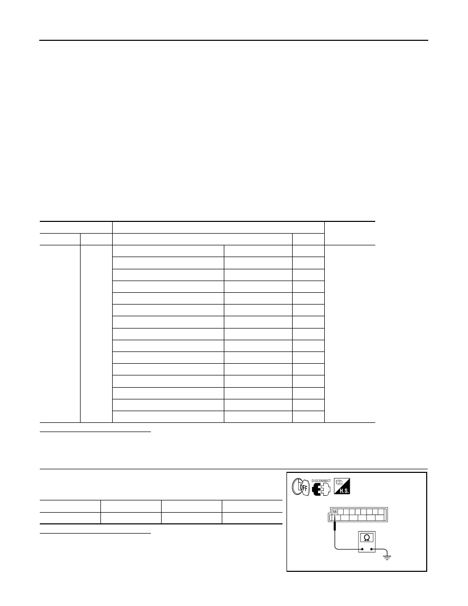
CHECK BATTERY SAVER OUTPUT/POWER SUPPLY SHORT CIRCUIT
Check continuity between BCM connector M20 terminal 56 and
ground.
Is the inspection result normal?
YES
>> Check that each interior room lamp has no internal short
circuit.
NO
>> Repair the harness or connectors.
BCM
Interior room lamp
Continuity
Connector
Terminal
Connector
Terminal
M20
56
Ignition keyhole illumination
M150
1
Yes
Front step lamp LH
D11
1
Front step lamp RH
D109
1
Door mirror LH
D4
12
Door mirror RH
D107
12
Rear step lamp LH
D206
1
Rear step lamp RH
D306
1
Foot lamp LH
M99
1
Foot lamp RH
M100
1
Front room/map lamp assembly
R102
6
Vanity lamp LH
R3
1
Vanity lamp RH
R8
1
Cargo lamp
B153
2
Personal lamp 2nd row
R203
3
Personal lamp 3rd row
R205
3
Connector
Terminal
—
Continuity
M20
56
Ground
No
ALLIA0409GB
INTERIOR ROOM LAMP CONTROL CIRCUIT
INL-19
< COMPONENT DIAGNOSIS >
C
D
E
F
G
H
I
J
K
M
A
B
INL
N
O
P
INTERIOR ROOM LAMP CONTROL CIRCUIT
Description
INFOID:0000000005146730
Controls the following interior room lamps (ground side) by PWM signal
• Puddle lamps
• Front room/map lamp assembly
• Personal lamp 2nd row
• Personal lamp 3rd row
NOTE:
PWM signal control period is approximately 250 Hz (in the gradual brightening/dimming).
Component Function Check
INFOID:0000000005146731
CAUTION:
Before performing the diagnosis, check that the following is normal.
• Battery saver output/power supply
• Front room/map lamp bulbs
• Personal lamp bulbs
• Puddle lamp bulbs
1.
CHECK INTERIOR ROOM LAMP CONTROL FUNCTION
CONSULT-III
1. Switch the front room/map lamp assembly switch to DOOR.
2. Turn ignition switch ON.
3. Select “INT LAMP” of BCM (INT LAMP) active test item.
4. While operating the test item, check that each interior room lamp turns ON/OFF (gradual brightening/dim-
ming).
Is the inspection result normal?
YES
>> Interior room lamp control circuit is normal.
NO
>> Refer to
.
Diagnosis Procedure
INFOID:0000000005146732
Regarding Wiring Diagram information, refer to
.
1.
CHECK INTERIOR ROOM LAMP CONTROL OUTPUT
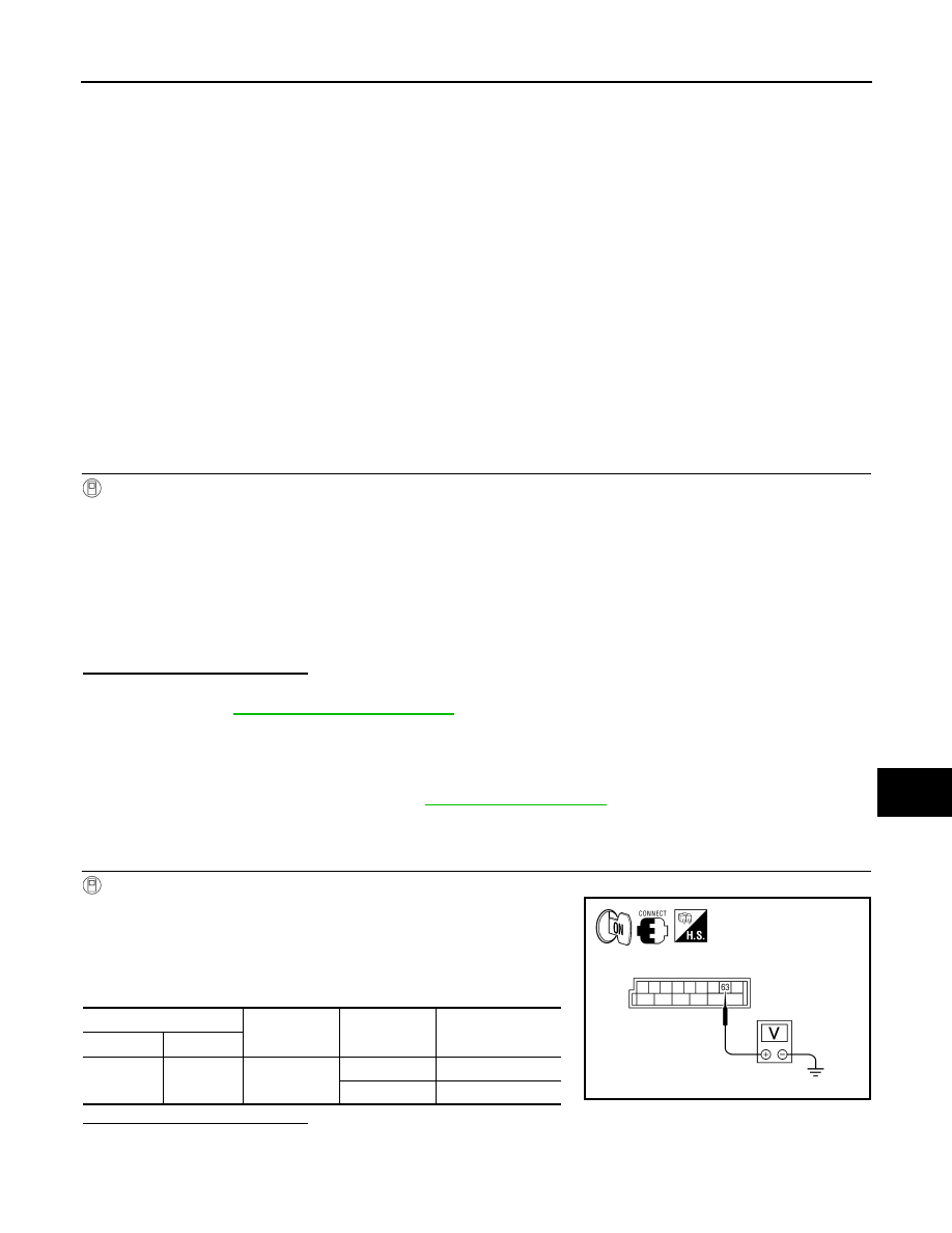
CONSULT-III
1. Switch the front room/map lamp assembly switch to DOOR.
2. Turn ignition switch ON.
3. Select “INT LAMP” of BCM (INT LAMP) active test item.
4. While operating the test item, check voltage between BCM con-
nector M20 terminal 63 and ground.
Is the inspection result normal?
YES
>> Interior room lamp control circuit is operating normally.
Fixed ON>>GO TO 3
Fixed OFF>>GO TO 2
ON
: Interior room lamp gradual brightening
OFF
: Interior room lamp gradual dimming
(+)
(-)
INT LAMP
Voltage
Connector
Terminal
M20
63
Ground
ON
0V
OFF
Battery voltage
ALLIA0410GB
Нет комментариевНе стесняйтесь поделиться с нами вашим ценным мнением.
Текст