Infiniti QX56 (JA60). Manual — part 620

INL-8
< FUNCTION DIAGNOSIS >
INTERIOR ROOM LAMP CONTROL SYSTEM
Component Description
INFOID:0000000005146718
13. Rear step lamp LH D206
Rear step lamp RH D306
14. Cargo lamp B153
15. Personal lamp 3rd row R205
16. Personal lamp 2nd row R203
Part name
Description
BCM
Provides power and ground and controls timer functions for the
interior room lamps, step lamps and cargo lamp.
Key switch and ignition knob switch
Provides key in ignition status to the BCM.
Door switches
Provides door OPEN/CLOSED status to the BCM.
Glass hatch switch
Provides glass hatch OPEN/CLOSED status to the BCM.
Back door latch
Provides back door OPEN/CLOSED status to the BCM.
Power window and door lock/unlock switch RH
Provides door lock/unlock position switch RH status to the BCM.
Main power window and door lock/unlock switch [front door lock
assembly LH (key cylinder switch)].
Provides door lock/unlock position switch LH status to the BCM.
ILLUMINATION CONTROL SYSTEM
INL-9
< FUNCTION DIAGNOSIS >
C
D
E
F
G
H
I
J
K
M
A
B
INL
N
O
P
ILLUMINATION CONTROL SYSTEM
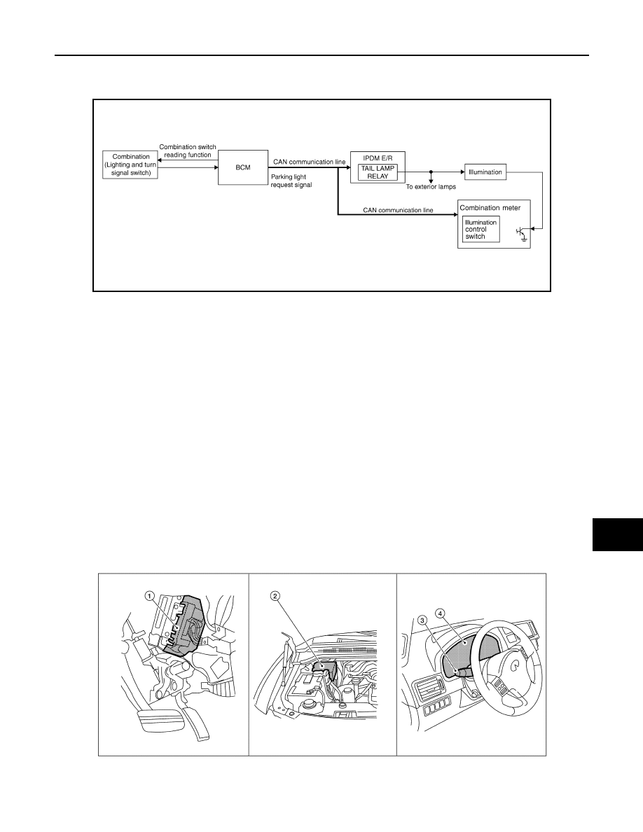
System Diagram
INFOID:0000000005358668
System Description
INFOID:0000000005358669
The illumination lamps operation is dependent upon the position of the combination switch (lighting and turn
signal switch). When the combination switch (lighting and turn signal switch) is placed in the 1ST or 2ND posi-
tion (or if the auto light system is activated) the BCM (body control module) receives input requesting the park-
ing lamps to illuminate. This input is communicated to the IPDM E/R (intelligent power distribution module
engine room) via the CAN communication lines. The CPU (central processing unit) of the IPDM E/R controls
the tail lamp relay coil. When energized, this relay directs power to the parking and illumination lamps, which
then illuminate.
BATTERY SAVER CONTROL
When the combination switch (lighting and turn signal switch) is in the 1ST or 2ND position and the ignition
switch is turned from ON or ACC to OFF, the battery saver control feature is activated. Under this condition,
the illumination lamps remain illuminated for 30 minutes unless the combination switch (lighting and turn signal
switch) position is changed. If the combination switch (lighting and turn signal switch) position is changed, then
the illumination lamps are turned off after a 30 second delay. When the combination switch (lighting and turn
signal switch) is turned from OFF to 1ST or 2ND position (or if auto light system is activated) after illumination
lamps have been turned off by the battery saver control, the illumination lamps illuminate again.
Component Parts Location
INFOID:0000000005146721
AWLIA1754GB
AWLIA0398ZZ

INL-10
< FUNCTION DIAGNOSIS >
ILLUMINATION CONTROL SYSTEM
Component Description
INFOID:0000000005358670
1.
BCM M18, M20 (view with instrument
lower panel LH removed)
2.
IPDM E/R E122, E123, E124
3.
Combination switch (lighting and turn
signal switch) M28
4.
Combination meter (illumination con-
trol switch) M23, M24
Part name
Description
BCM
The BCM monitors the lighting switch position with the combina-
tion switch reading function. The BCM requests, via CAN com-
munication, that the IPDM E/R activate the tail lamp relay.
IPDM E/R
The IPDM E/R activates the tail lamp relay based on inputs re-
ceived from the BCM via the CAN communication network.
Combination meter (illumination control switch)
The illumination control switch is a part of the combination meter.
The combination meter controls illumination intensity by varying
ground to the illumination lamps based on the illumination control
switch position.
Combination switch (lighting and turn signal switch)
The combination switch provides input to the BCM about the light-
ing switch position.

DIAGNOSIS SYSTEM (BCM)
INL-11
< FUNCTION DIAGNOSIS >
C
D
E
F
G
H
I
J
K
M
A
B
INL
N
O
P
DIAGNOSIS SYSTEM (BCM)
COMMON ITEM
COMMON ITEM : CONSULT-III Function (BCM - COMMON ITEM)
INFOID:0000000005356686
APPLICATION ITEM
CONSULT-III performs the following functions via CAN communication with BCM.
SYSTEM APPLICATION
BCM can perform the following functions for each system.
NOTE:
It can perform the diagnosis modes except the following for all sub system selection items.
INT LAMP
Diagnosis mode
Function Description
WORK SUPPORT
Changes the setting for each system function.
SELF-DIAG RESULTS
Displays the diagnosis results judged by BCM. Refer to
CAN DIAG SUPPORT MNTR
Monitors the reception status of CAN communication viewed from BCM.
DATA MONITOR
The BCM input/output signals are displayed.
ACTIVE TEST
The signals used to activate each device are forcibly supplied from BCM.
ECU IDENTIFICATION
The BCM part number is displayed.
CONFIGURATION
• Enables to read and save the vehicle specification.
• Enables to write the vehicle specification when replacing BCM.
System
Sub system selection item
Diagnosis mode
WORK SUPPORT
DATA MONITOR
ACTIVE TEST
BCM
BCM
×
Door lock
DOOR LOCK
×
×
×
Rear window defogger
REAR DEFOGGER
×
Warning chime
BUZZER
×
×
Interior room lamp timer
INT LAMP
×
×
×
Remote keyless entry system
MULTI REMOTE ENT
×
×
Exterior lamp
HEAD LAMP
×
×
×
Wiper and washer
WIPER
×
×
×
Turn signal and hazard warning lamps FLASHER
×
×
Air conditioner
AIR CONDITONER
×
Intelligent Key system
INTELLIGENT KEY
×
Combination switch
COMB SW
×
Immobilizer
IMMU
×
×
Interior room lamp battery saver
BATTERY SAVER
×
×
×
Back door open
TRUNK
×
×
RAP (retained accessory power)
RETAINED PWR
×
×
×
Signal buffer system
SIGNAL BUFFER
×
×
TPMS (tire pressure monitoring sys-
tem)
AIR PRESSURE MONITOR
×
×
×
Vehicle security system
THEFT ALM
×
×
×
Panic alarm system
PANIC ALARM
×
Нет комментариевНе стесняйтесь поделиться с нами вашим ценным мнением.
Текст