Infiniti F50. Manual — part 487

DTC P1491 VACUUM CUT VALVE BYPASS VALVE
EC-589
C
D
E
F
G
H
I
J
K
L
M
A
EC
7.
CHECK BYPASS HOSE
Check bypass hoses for clogging.
OK or NG
OK
>> GO TO 8.
NG
>> Repair or replace hoses.
8.
CHECK VACUUM CUT VALVE BYPASS VALVE
Refer to
EC-590, "Component Inspection"
OK or NG
OK
>> GO TO 9.
NG
>> Replace vacuum cut valve bypass valve.
9.
CHECK VACUUM CUT VALVE
Refer to
EC-590, "Component Inspection"
OK or NG
OK
>> GO TO 10.
NG
>> Replace vacuum cut valve.
10.
CHECK EVAP CONTROL SYSTEM PRESSURE SENSOR HOSE
1.
Turn ignition switch “OFF”.
2.
Check disconnection or improper connection of hose connected to EVAP control system pressure sensor.
OK or NG
OK
>> GO TO 11.
NG
>> Repair or replace.
11.
CHECK EVAP CONTROL SYSTEM PRESSURE SENSOR CONNECTOR
1.
Disconnect EVAP control system pressure sensor harness connector.
2.
Check connectors for water.
OK or NG
OK
>> GO TO 12.
NG
>> Replace EVAP control system pressure sensor.
12.
CHECK EVAP CONTROL SYSTEM PRESSURE SENSOR
Refer to
EC-365, "Component Inspection"
OK or NG
OK
>> GO TO 13.
NG
>> Replace EVAP control system pressure sensor.
13.
CHECK RUBBER TUBE FOR CLOGGING
1.
Disconnect rubber tube connected to EVAP canister vent control valve.
2.
Check the rubber tube for clogging.
OK or NG
OK
>> GO TO 14.
NG
>> Clean the rubber tube using an air blower.
Water should not exist.
EC-590
DTC P1491 VACUUM CUT VALVE BYPASS VALVE
14.
CHECK EVAP CANISTER VENT CONTROL VALVE
Refer to
EC-558, "Component Inspection"
OK or NG
OK
>> GO TO 15.
NG
>> Replace EVAP canister vent control valve.
15.
CHECK REFUELING EVAP VAPOR CUT VALVE
Refer to
EC-693, "Component Inspection"
OK or NG
OK
>> GO TO 16.
NG
>> Replace fuel tank.
16.
CHECK REFUELING CONTROL VALVE
Refer to
EC-693, "Component Inspection"
OK or NG
OK
>> GO TO 17.
NG
>> Replace fuel tank.
17.
CHECK INTERMITTENT INCIDENT
Refer to
EC-132, "TROUBLE DIAGNOSIS FOR INTERMITTENT INCIDENT"
.
>> INSPECTION END
Component Inspection
EBS00MM6
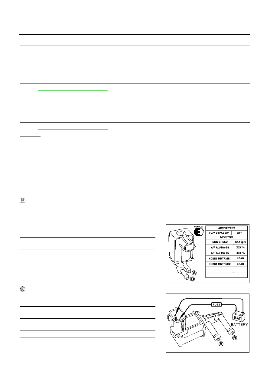
VACUUM CUT VALVE BYPASS VALVE
With CONSULT-II
1.
Reconnect all harness connectors disconnected.
2.
Turn ignition switch ON.
3.
Perform “VC/V BYPASS/V” in “ACTIVE TEST” mode.
4.
Check air passage continuity and operation delay time under the
following conditions.
Operation takes less than 1 second.
With GST
Check air passage continuity and operation delay time under the fol-
lowing conditions.
Operation takes less than 1 second.
Condition
VC/V BYPASS/V
Air passage continuity
between A and B
ON
Yes
OFF
No
PBIB0159E
Condition
Air passage continuity
between A and B
12V direct current supply between
terminals 1 and 2
Yes
No supply
No
PBIB0160E

DTC P1491 VACUUM CUT VALVE BYPASS VALVE
EC-591
C
D
E
F
G
H
I
J
K
L
M
A
EC
VACUUM CUT VALVE
Check vacuum cut valve as follows:
●
Plug port C and D with fingers.
●
Apply vacuum to port A and check that there is no suction from
port B .
●
Apply vacuum to port B and check that there is suction from
port A .
●
Blow air in port B and check that there is a resistance to flow out
of port A .
●
Open port C and D .
●
Blow air in port A check that air flows freely out of port C .
●
Blow air in port B check that air flows freely out of port D .
SEF379Q

EC-592
DTC P1706 PNP SWITCH
DTC P1706 PNP SWITCH
PFP:32006
Component Description
EBS00MM7
When the gear position is “P” or “N”, park/neutral position (PNP) switch is “ON”.
ECM detects the position because the continuity of the line (the “ON” signal) exists.
CONSULT-II Reference Value in Data Monitor Mode
EBS00MM8
Specification data are reference values.
On Board Diagnosis Logic
EBS00MM9
DTC Confirmation Procedure
EBS00MMA
CAUTION:
Always drive vehicle at a safe speed.
NOTE:
If “DTC Confirmation Procedure” has been previously conducted, always turn ignition switch “OFF” and wait at
least 10 seconds before conducting the next test.
WITH CONSULT-II
1.
Turn ignition switch “ON”.
2.
Select “P/N POSI SW” in “DATA MONITOR” mode with CON-
SULT-II. Then check the “P/N POSI SW” signal under the follow-
ing conditions.
If NG, go to
EC-595, "Diagnostic Procedure"
If OK, go to following step.
3.
Select “DATA MONITOR” mode with CONSULT-II.
4.
Start engine and warm it up to normal operating temperature.
5.
Maintain the following conditions for at least 60 consecutive sec-
onds.
6.
If 1st trip DTC is detected, go to
EC-595, "Diagnostic Procedure"
.
MONITOR ITEM
CONDITION
SPECIFICATION
P/N POSI SW
●
Ignition switch: ON
Selector lever: P or N
ON
Selector lever: Except above
OFF
DTC No.
Trouble diagnosis name
DTC detecting condition
Possible cause
P1706
1706
Park/neutral position
switch
The signal of the park/neutral position (PNP)
switch is not changed in the process of engine
starting and driving.
●
Harness or connectors
[The park/neutral position (PNP) switch
circuit is open or shorted.]
●
Park/neutral position (PNP) switch
Position (Selector lever)
Known-good signal
“N” or “P” position
ON
Except the above position
OFF
ENG SPEED
More than 1,200 rpm
COOLAN TEMP/S
More than 70
°
C (158
°
F)
B/FUEL SCHDL
2.0 - 31 msec
VHCL SPEED SE
More than 64 km/h (40 MPH)
Selector lever
Suitable position
SEF212Y
SEF213Y
Нет комментариевНе стесняйтесь поделиться с нами вашим ценным мнением.
Текст