Infiniti F50. Manual — part 395
DTC P0133, P0153 HO2S1
EC-221
C
D
E
F
G
H
I
J
K
L
M
A
EC
DTC P0133, P0153 HO2S1
PFP:22690
Component Description
ABS002GU
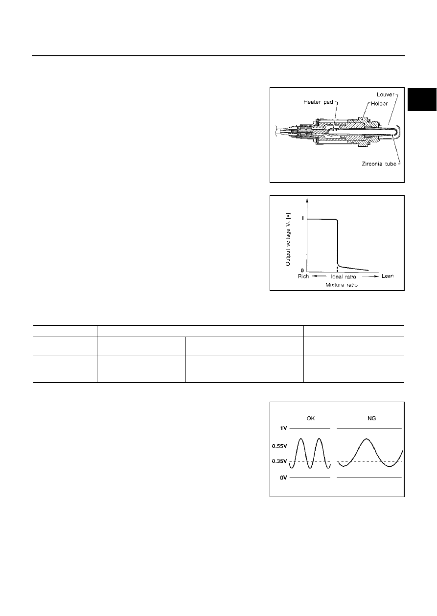
The heated oxygen sensor 1 is placed into the exhaust manifold. It
detects the amount of oxygen in the exhaust gas compared to the
outside air. The heated oxygen sensor 1 has a closed-end tube
made of ceramic zirconia. The zirconia generates voltage from
approximately 1V in richer conditions to 0V in leaner conditions. The
heated oxygen sensor 1 signal is sent to the ECM. The ECM adjusts
the injection pulse duration to achieve the ideal air-fuel ratio. The
ideal air-fuel ratio occurs near the radical change from 1 to 0V.
CONSULT-II Reference Value in Data Monitor Mode
ABS002GV
Specification data are reference values.
On Board Diagnosis Logic
ABS002GW
To judge the malfunction of heated oxygen sensor 1, this diagnosis
measures response time of heated oxygen sensor 1 signal. The time
is compensated by engine operating (speed and load), fuel feedback
control constant, and heated oxygen sensor 1 temperature index.
Judgment is based on whether the compensated time (heated oxy-
gen sensor 1 cycling time index) is inordinately long or not.
SEF463R
SEF288D
MONITOR ITEM
CONDITION
SPECIFICATION
HO2S1 (B1)
HO2S1 (B2)
●
Engine: After warming up
Maintaining engine speed at 2,000 rpm
0 - 0.3V
←→
Approx. 0.6 - 1.0V
HO2S1 MNTR (B1)
HO2S1 MNTR (B2)
●
Engine: After warming up
Maintaining engine speed at 2,000 rpm
LEAN
←→
RICH
Changes more than 5 times during
10 seconds.
SEF010V

EC-222
DTC P0133, P0153 HO2S1
DTC Confirmation Procedure
ABS002GX
CAUTION:
Always drive vehicle at a safe speed.
NOTE:
If “DTC Confirmation Procedure” has been previously conducted, always turn ignition switch “OFF” and wait at
least 10 seconds before conducting the next test.
TESTING CONDITION:
●
Always perform at a temperature above
−
10
°
C (14
°
F).
●
Before performing the following procedure, confirm that battery voltage is more than 11V at idle.
WITH CONSULT-II
1.
Start engine and warm it up to normal operating temperature.
2.
Stop engine and wait at least 10 seconds.
3.
Turn ignition switch “ON” and select “HO2S1 (B1) P0133” or “HO2S1 (B2) P0153” of “HO2S1” in “DTC
WORK SUPPORT” mode with CONSULT-II.
4.
Touch “START”.
5.
Start engine and let it idle for at least 3 minutes.
NOTE:
Never raise engine speed above 3,600 rpm after this step. If
the engine speed limit is exceeded, return to step 5.
6.
When the following conditions are met, “TESTING” will be dis-
played on the CONSULT-II screen. Maintain the conditions con-
tinuously until “TESTING” changes to “COMPLETED”. (It will
take approximately 40 to 50 seconds.)
If “TESTING” is not displayed after 5 minutes, retry from
step 2.
DTC No.
Trouble diagnosis name
DTC detecting condition
Possible cause
P0133
0133
(Bank 1)
Heated oxygen sensor 1
circuit slow response
The response of the voltage signal from the
sensor takes more than the specified time.
●
Harness or connectors
(The sensor circuit is open or shorted)
●
Heated oxygen sensor 1
●
Fuel pressure
●
Injectors
●
Intake air leaks
●
Exhaust gas leaks
●
PCV valve
●
Mass air flow sensor
P0153
0153
(Bank 2)
SEF338Z
ENG SPEED
1,350 - 2,400 rpm
Vehicle speed
More than 80 km/h (50 MPH)
B/FUEL SCHDL
1.6 - 12.0 msec
Selector lever
Suitable position
SEF339Z
DTC P0133, P0153 HO2S1
EC-223
C
D
E
F
G
H
I
J
K
L
M
A
EC
7.
Make sure that “OK” is displayed after touching “SELF-DIAG
RESULTS”. If “NG” is displayed, refer to
Overall Function Check
ABS002GY
Use this procedure to check the overall function of the heated oxygen sensor 1 circuit. During this check, a
DTC might not be confirmed.
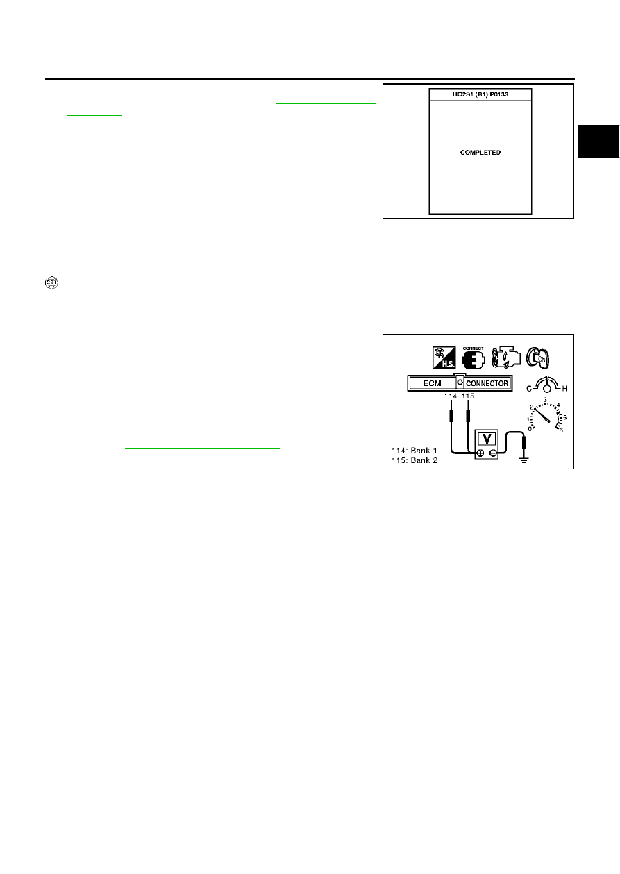
WITH GST
1.
Start engine and warm it up to normal operating temperature.
2.
Set voltmeter probes between ECM terminal 114 [HO2S1(B1) signal] or 115 [HO2S1(B2) signal] and
engine ground.
3.
Check the following with engine speed held at 2,000 rpm con-
stant under no load.
–
The voltage fluctuates between 0 to 0.3V and 0.6 to 1.0V more
than 5 times within 10 seconds.
4.
EC-227, "Diagnostic Procedure"
SEF658Y
1 time:
0 - 0.3V
→
0.6 - 1.0V
→
0 - 0.3V
2
times:
0 - 0.3V
→
0.6 - 1.0V
→
0 - 0.3V
→
0.6 - 1.0V
→
0 - 0.3V
PBIB0063E

EC-224
DTC P0133, P0153 HO2S1
Wiring Diagram
ABS002GZ
BANK 1
TBWM0143E
Нет комментариевНе стесняйтесь поделиться с нами вашим ценным мнением.
Текст