Infiniti FX35, FX50 (S51). Manual — part 206

BCS
INSPECTION AND ADJUSTMENT
BCS-5
< BASIC INSPECTION >
C
D
E
F
G
H
I
J
K
L
B
A
O
P
N
CONFIGURATION (BCM) : Configuration list
INFOID:0000000005249298
CAUTION:
Thoroughly read and understand the vehicle specification. Incorrect settings may result in abnormal
control of ECU.
⇔
: Items which confirm vehicle specifications
MANUAL SETTING ITEM
NOTE
Items
Setting value
RAIN SENSOR CONFIG
WITH
⇔
WITHOUT
—
DTRL
WITH
⇔
WITHOUT
• WITH: With daytime running light system
• WITHOUT: Without daytime running light system
AUTO SETTING ITEM
NOTE
Items
Setting value
UNLOCK WITH SHOCK
WITH
—
AUTO DOOR LOCK SPEED
MODE1
—
ROOF FUNCTION
W/O REQ SW
—
ROOM LAMP ON TIME
MODE5
—
ROOM LAMP OFF TIME
MODE5
—
Trunk/Glass Hatch select
Glass Hatch
Even on a vehicle without glass hatch. It displays “Glass
Hatch”.
TR OPEN SW (INT)
MODE1
—
DI LMP VARIAT
MODE2
—
LIGHT RECOG
MODE4
—
TRANSMISSION
AT with ABS
—
BCM AC CONTROL
MODE1
—
WELCOME LIGHT TIMER2
MODE4
—
TPMS
TPMS SBF
—
RAIN SEN TYPE
MODE3
—
Key Fob Type
MODE9
—
WELCOME LIGHT OP SET
WITH
—

BCS-6
< SYSTEM DESCRIPTION >
BODY CONTROL SYSTEM
SYSTEM DESCRIPTION
BODY CONTROL SYSTEM
System Description
INFOID:0000000005249299
OUTLINE
• BCM (Body Control Module) controls the various electrical components. It inputs the information required to
the control from CAN communication and the signal received from each switch and sensor.
• BCM has combination switch reading function for reading the operation status of combination switches (light,
turn signal, wiper and washer) in addition to a function for controlling the operation of various electrical com-
ponents. It also has the signal transmission function as the passed point of signal and the power saving con-
trol function that reduces the power consumption with the ignition switch OFF.
• BCM is equipped with the diagnosis function that performs the diagnosis with CONSULT-III and various set-
tings.
BCM CONTROL FUNCTION LIST
System
Reference
Combination switch reading system
Signal buffer system
Power consumption control system
Auto light system
Turn signal and hazard warning lamp system
Headlamp system
Parking, license plate and tail lamps system
Front fog lamp system
Exterior lamp battery saver system
Daytime running light system
Interior room lamp control system
Step lamp system
Interior room lamp battery saver system
Front wiper and washer system
•
WW-5, "WITH RAIN SENSOR : System Diagram"
(With
rain sensor)
•
WW-9, "WITHOUT RAIN SENSOR : System Diagram"
(Without rain sensor)
Rear wiper and washer system
Warning chime system
WCS-5, "WARNING CHIME SYSTEM : System Diagram"
Door lock system
Infiniti Vehicle Immobilizer System (IVIS) - NATS
Vehicle security system
Panic alarm
DLK-28, "REMOTE KEYLESS ENTRY FUNCTION : Sys-
tem Diagram"
Automatic drive positioner system
ADP-13, "AUTOMATIC DRIVE POSITIONER SYSTEM :
System Diagram"
Rear window defogger system
BCS
BODY CONTROL SYSTEM
BCS-7
< SYSTEM DESCRIPTION >
C
D
E
F
G
H
I
J
K
L
B
A
O
P
N
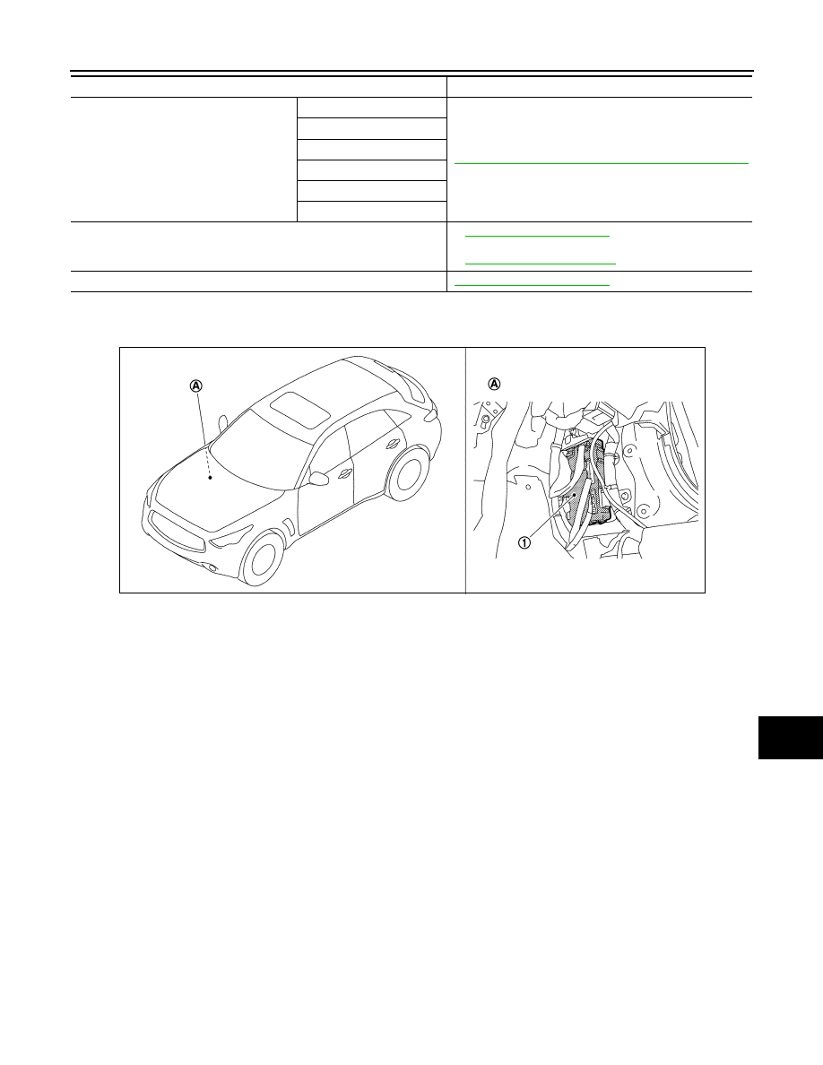
Component Parts Location
INFOID:0000000005249300
Intelligent Key system/engine start system
Door lock unlock function
DLK-16, "INTELLIGENT KEY SYSTEM : System Diagram"
Remote keyless function
Back door open function
Warning function
Key reminder function
Engine start function
Power window system
•
(Front & rear window anti-
pinch)
•
(Front window anti-pinch)
Retained accessory power (RAP) system
System
Reference
1.
BCM
A.
Dash side lower (passenger side)
JPMIA1122ZZ
BCS-8
< SYSTEM DESCRIPTION >
COMBINATION SWITCH READING SYSTEM
COMBINATION SWITCH READING SYSTEM
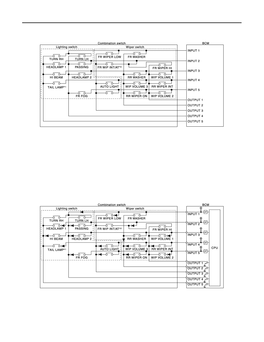
System Diagram
INFOID:0000000005612129
NOTE:
• *1: TAIL LAMP switch links lighting switch 1ST position.
• *2: “FR WIP INT/AT” is FR WIPER INT/AUTO.
System Description
INFOID:0000000005612130
OUTLINE
• BCM reads the status of the combination switch (light, turn signal, wiper and washer) and recognizes the
status of each switch.
• BCM is a combination of 5 output terminals (OUTPUT 1 - 5) and 5 input terminals (INPUT 1 - 5). It reads a
maximum of 20 switch status.
COMBINATION SWITCH MATRIX
Combination switch circuit
NOTE:
• *1: TAIL LAMP switch links lighting switch 1ST position.
• *2: “FR WIP INT/AT” is FR WIPER INT/AUTO.
JMMIA0292GB
JMMIA0293GB
Нет комментариевНе стесняйтесь поделиться с нами вашим ценным мнением.
Текст