Infiniti FX35, FX50 (S51). Manual — part 207
BCS
COMBINATION SWITCH READING SYSTEM
BCS-9
< SYSTEM DESCRIPTION >
C
D
E
F
G
H
I
J
K
L
B
A
O
P
N
Combination switch INPUT-OUTPUT system list
NOTE:
Headlamp has a dual system switch.
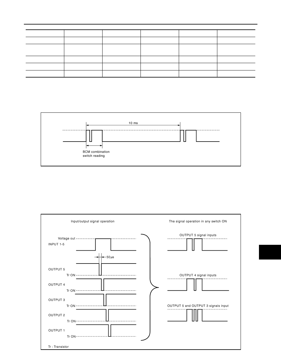
COMBINATION SWITCH READING FUNCTION
Description
• BCM reads the status of the combination switch at 10 ms interval normally.
NOTE:
BCM reads the status of the combination switch at 60 ms interval when BCM is controlled at low power con-
sumption mode.
• BCM operates as follows and judges the status of the combination switch.
- INPUT 1 - 5 outputs the voltage waveforms of 5 systems simultaneously.
- It operates the transistor on OUTPUT side in the following order: OUTPUT 5
→
4
→
3
→
2
→
1.
- The voltage waveform of INPUT corresponding to the formed circuit changes according to the operation of
the transistor on OUTPUT side if any (1 or more) switches are ON.
- It reads this change of the voltage as the status signal of the combination switch.
System
OUTPUT 1
OUTPUT 2
OUTPUT 3
OUTPUT 4
OUTPUT 5
INPUT 1
—
FR WASHER
FR WIPER LOW
TURN LH
TURN RH
INPUT 2
FR WIPER HI
—
FR WIPER INT/
AUTO
PASSING
HEADLAMP 1
INPUT 3
WIP VOLUME 1
—
—
HEADLAMP 2
HI BEAM
INPUT 4
—
WIP VOLUME 3
AUTO LIGHT
—
TAIL LAMP
INPUT 5
WIP VOLUME 2
—
—
FR FOG
—
JPMIA0067GB
JPMIA0068GB

BCS-10
< SYSTEM DESCRIPTION >
COMBINATION SWITCH READING SYSTEM
Operation Example
In the following operation example, the combination of the status signals of the combination switch is replaced
as follows: INPUT 1 - 5 to “1 - 5” and OUTPUT 1 - 5 to “A - E”.
Example 1: When a switch (TURN RH switch) is turned ON
• The circuit between INPUT 1 and OUTPUT 5 is formed when the TURN RH switch is turned ON.
• BCM detects the combination switch status signal “1E” when the signal of OUTPUT 5 is input to INPUT 1.
• BCM judges that the TURN RH switch is ON when the signal “1E” is detected.
Example 2: When some switches (turn RH switch, front wiper LO switch) are turned ON
• The circuits between INPUT 1 and OUTPUT 5 and between INPUT 1 and OUTPUT 3 are formed when the
TURN RH switch and FR WIPER LOW switch are turned ON.
• BCM detects the combination switch status signal “1CE” when the signals of OUTPUT 3 and OUTPUT 5 are
input to INPUT 1.
• BCM judges that the TURN RH switch and FR WIPER LOW switch are ON when the signal “1CE” is
detected.
WIPER VOLUME DIAL POSITION
BCM judges the wiper volume dial 1 - 7 by the status of WIP VOLUME 1, 2 and 3 switches.
JMMIA0294GB
JMMIA0295GB
Wiper volume dial position
Switch status
WIP VOLUME 1
WIP VOLUME 2
WIP VOLUME 3
1
ON
ON
ON
2
ON
ON
OFF

BCS
COMBINATION SWITCH READING SYSTEM
BCS-11
< SYSTEM DESCRIPTION >
C
D
E
F
G
H
I
J
K
L
B
A
O
P
N
NOTE:
For details of wiper volume dial position, refer to
WW-5, "WITH RAIN SENSOR : System Description"
(with rain sensor),
OUT RAIN SENSOR : System Description"
3
ON
OFF
OFF
4
OFF
OFF
OFF
5
OFF
OFF
ON
6
OFF
ON
ON
7
OFF
ON
OFF
Wiper volume dial position
Switch status
WIP VOLUME 1
WIP VOLUME 2
WIP VOLUME 3

BCS-12
< SYSTEM DESCRIPTION >
SIGNAL BUFFER SYSTEM
SIGNAL BUFFER SYSTEM
System Diagram
INFOID:0000000005612131
System Description
INFOID:0000000005612132
OUTLINE
BCM has the signal transmission function that outputs/transmits each input/received signal to each unit.
Signal transmission function list
JMMIA0247GB
Signal name
Input
Output
Description
• Ignition switch ON signal
• Ignition switch signal
Push-button ignition switch
(Push switch)
• IPDM E/R (CAN)
• Driver seat control unit (CAN)
Inputs the push-button ignition
switch (push switch) signal and
transmits the ignition switch sta-
tus judged with BCM via CAN
communication.
Door switch signal
Any door switch
• Combination meter (through
unified meter and A/C amp.)
(CAN)
• IPDM E/R (CAN)
• Driver seat control unit (CAN)
Inputs the door switch signal
and transmits it via CAN com-
munication.
Oil pressure switch signal
IPDM E/R (CAN)
Combination meter (through
unified meter and A/C amp.)
(CAN)
Transmits the received oil pres-
sure switch signal via CAN
communication.
Stop lamp switch signal
• Stop lamp switch
• ICC brake hold relay (With
ICC)
TCM (CAN)
Inputs the stop lamp switch 1
signal and stop lamp switch 2
signal, and transmits it via CAN
communication.
Нет комментариевНе стесняйтесь поделиться с нами вашим ценным мнением.
Текст