Infiniti FX35, FX50 (S51). Manual — part 1874

SHIFT POSITION INDICATOR CIRCUIT
TM-303
< DTC/CIRCUIT DIAGNOSIS >
[7AT: RE7R01B (VK50VE)]
C
E
F
G
H
I
J
K
L
M
A
B
TM
N
O
P
SHIFT POSITION INDICATOR CIRCUIT
Description
INFOID:0000000005250317
TCM transmit the switch signals to unified meter and A/C amp. by CAN communication line. Then manual
mode switch position is indicated on the shift position indicator.
Component Function Check
INFOID:0000000005250318
1.
CHECK A/T INDICATOR
1.
Start the engine.
2.
Check the actual selector lever position (“P”, “R”, “N” and “D”) and the indication of the shift position indi-
cator mutually coincide.
3.
Drive vehicle in the manual mode, and then check that the actual gear position and the indication of the
position indicator mutually coincide when the selector lever is shifted to “UP (+ side)” or “DOWN (
−
side)”
side (1GR
⇔
7GR).
Is the inspection result normal?
YES
>> INSPECTION END
NO
>> Go to
Diagnosis Procedure
INFOID:0000000005250319
1.
CHECK INPUT SIGNALS
With CONSULT-III
1.
Start the engine.
2.
Select “SLCT LVR POSI” in “Data Monitor” in “TRANSMISSION”.
3.
Check the actual selector lever position (“P”, “R”, “N” and “D”) and the indication of the “SLCT LVR POSI”
mutually coincide. Refer to
.
4.
Drive vehicle in the manual mode, and then check that the actual gear position and the indication of the
“SLCT LVR POSI” mutually coincide when the selector lever is shifted to the “UP (+ side)” or “DOWN (
−
side)” side (1GR
⇔
7GR). Refer to
.
Is the inspection result normal?
YES
>> INSPECTION END
NO-1 [The actual gear position does not change, or shifting into the manual mode is not possible (no gear
shifting in the manual mode possible). Or the shift position indicator is not indicated.]>>•Check
manual
TM-294, "Component Inspection (Manual Mode Switch)"
• Check A/T main system (Fail-safe function actuated).
- Perform “Self Diagnostic Results” mode for “TRANSMISSION”. Refer to
.
NO-2 (The actual gear position changes, but the shift position indicator is not indicated.)>>•Perform
“Self
Diagnostic Results” mode for “TRANSMISSION”. Refer to
NO-3 (The actual gear position and the indication on the shift position indicator do not coincide.)>>•Perform
“Self Diagnostic Results” mode for “TRANSMISSION”. Refer to
.
NO-4 (Only a specific position or positions is/are not indicated on the shift position indicator.)>>•Check
the
unified meter and A/C amp. Refer to
.
TM-304
< DTC/CIRCUIT DIAGNOSIS >
[7AT: RE7R01B (VK50VE)]
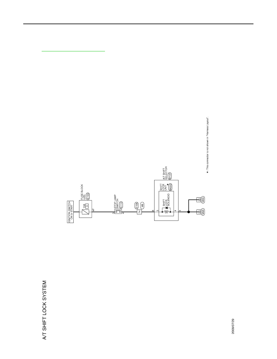
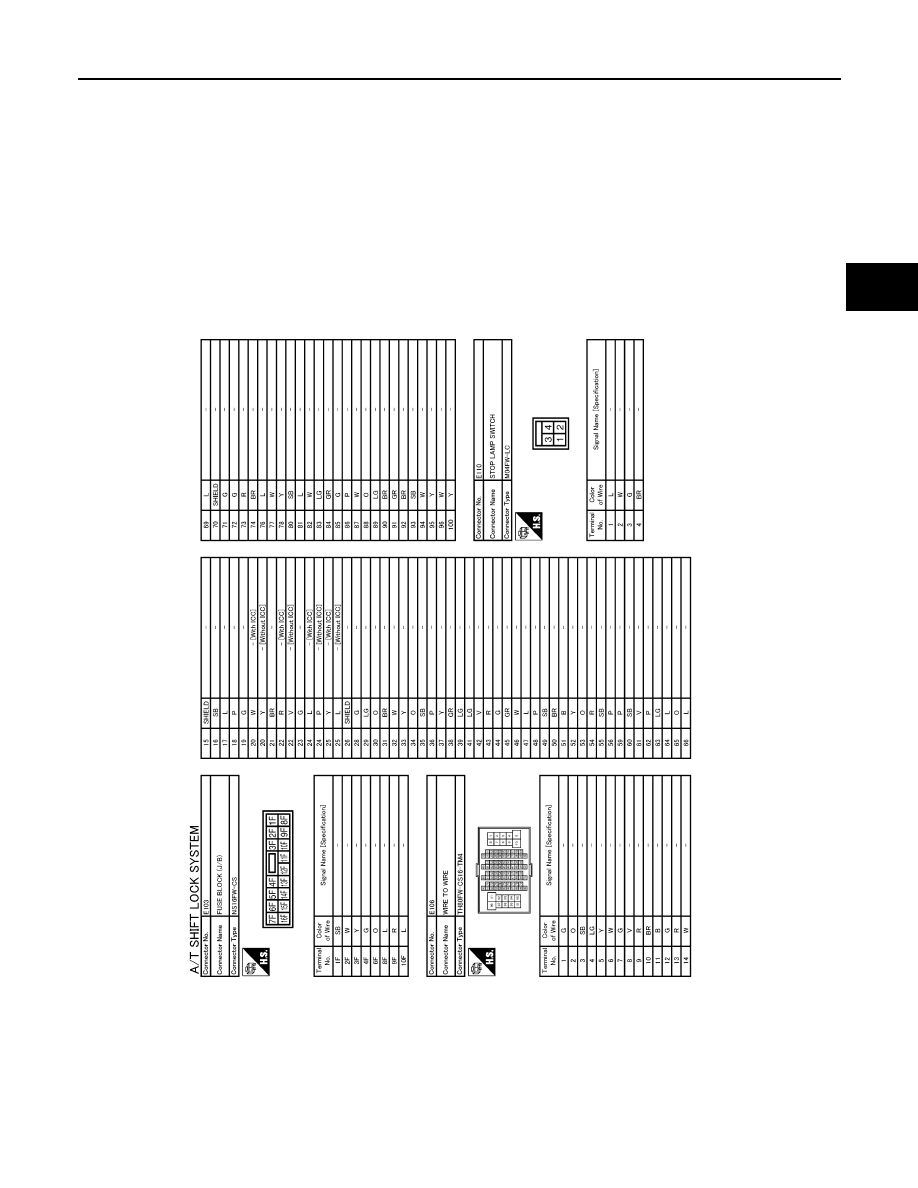
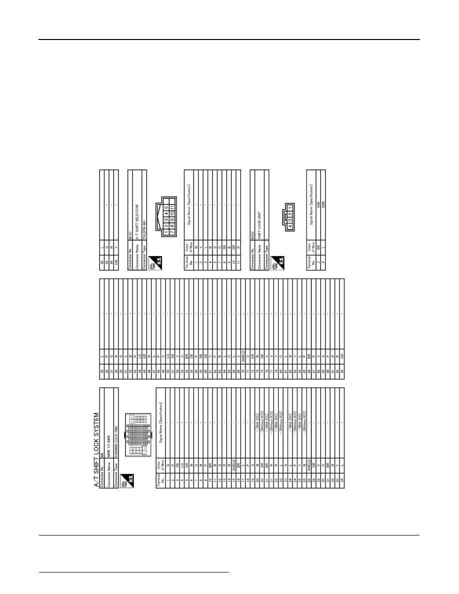
SHIFT LOCK SYSTEM
SHIFT LOCK SYSTEM
Description
INFOID:0000000005530872
Wiring Diagram - A/T SHIFT LOCK SYSTEM -
INFOID:0000000005530873
JCDWA0565GB
SHIFT LOCK SYSTEM
TM-305
< DTC/CIRCUIT DIAGNOSIS >
[7AT: RE7R01B (VK50VE)]
C
E
F
G
H
I
J
K
L
M
A
B
TM
N
O
P
JCDWA0566GB
TM-306
< DTC/CIRCUIT DIAGNOSIS >
[7AT: RE7R01B (VK50VE)]
SHIFT LOCK SYSTEM
Component Function Check
INFOID:0000000005530874
1.
CHECK A/T SHIFT LOCK OPERATION (PART 1)
1.
Turn ignition switch ON.
2.
Shift the selector lever to “P” position.
3.
Attempt to shift the selector lever to any other position with the brake pedal released.
Can the selector lever be shifted to any other position?
JCDWA0567GB
Нет комментариевНе стесняйтесь поделиться с нами вашим ценным мнением.
Текст