Infiniti FX35, FX50 (S51). Manual — part 1873
P2807 PRESSURE CONTROL SOLENOID G
TM-299
< DTC/CIRCUIT DIAGNOSIS >
[7AT: RE7R01B (VK50VE)]
C
E
F
G
H
I
J
K
L
M
A
B
TM
N
O
P
P2807 PRESSURE CONTROL SOLENOID G
Description
INFOID:0000000005250312
• The direct clutch solenoid valve is controlled by the TCM in response to signals transmitted from the trans-
mission range switch, output speed sensor and accelerator pedal position sensor. Gears will then be shifted
to the optimum position.
• The direct clutch solenoid valve controls the direct clutch control valve in response to a signal transmitted
from the TCM.
DTC Logic
INFOID:0000000005250313
DTC DETECTION LOGIC
DTC CONFIRMATION PROCEDURE
CAUTION:
Always drive vehicle at a safe speed.
NOTE:
If “DTC CONFIRMATION PROCEDURE” has been previously performed, always turn ignition switch
OFF. Then wait at least 10 seconds before performing the next test.
1.
PRECONDITIONING
If “DTC CONFIRMATION PROCEDURE” has been previously conducted, always turn ignition switch OFF and
wait at least 10 seconds before conducting the next test.
>> GO TO 2.
2.
CHECK DTC DETECTION
With CONSULT-III
1.
Start the engine.
2.
Select “BATTERY VOLT”, “MANU MODE SW”, “GEAR” and “VHCL/S SE-A/T” in “Data Monitor” in
“TRANSMISSION”.
3.
Drive vehicle and maintain the following conditions for 5 seconds or more.
4.
Perform “Self Diagnostic Results” in “TRANSMISSION”.
With GST
Follow the procedure “With CONSULT-III”.
Is “P2807” detected?
YES
>> Go to
NO
>> INSPECTION END
Diagnosis Procedure
INFOID:0000000005250314
1.
CHECK INTERMITTENT INCIDENT
GI-36, "Intermittent Incident"
.
Is the inspection result normal?
YES
>> Replace A/T assembly. Refer to
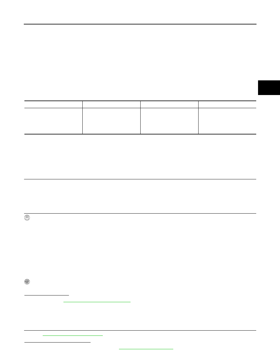
DTC
Trouble diagnosis name
DTC is detected if...
Possible cause
P2807
Pressure Control Solenoid G
The direct clutch solenoid valve
monitor value is 0.4 A or less
when the direct clutch solenoid
valve command value is more
than 0.75 A.
• Harness or connectors
(Solenoid valve circuit is
open or shorted.)
• Direct clutch solenoid valve
BATTERY VOLT
: 9 V or more
MANU MODE SW
: ON
GEAR
: 1st
VHCL/S SE-A/T
: 10 km/h (7 MPH) or more
TM-300
< DTC/CIRCUIT DIAGNOSIS >
[7AT: RE7R01B (VK50VE)]
P2807 PRESSURE CONTROL SOLENOID G
NO
>> Repair or replace damaged parts.
MAIN POWER SUPPLY AND GROUND CIRCUIT
TM-301
< DTC/CIRCUIT DIAGNOSIS >
[7AT: RE7R01B (VK50VE)]
C
E
F
G
H
I
J
K
L
M
A
B
TM
N
O
P
MAIN POWER SUPPLY AND GROUND CIRCUIT
Description
INFOID:0000000005523163
Supply power to TCM.
Diagnosis Procedure
INFOID:0000000005523164
1.
CHECK TCM POWER SOURCE (PART 1)
1.
Turn ignition switch OFF.
2.
Disconnect A/T assembly connector.
3.
Check voltage between A/T assembly vehicle side harness connector terminal and ground.
Is the inspection result normal?
YES
>> GO TO 2.
NO
>> GO TO 4.
2.
CHECK TCM POWER SOURCE (PART 2)
Check voltage between A/T assembly vehicle side harness connector terminals and ground.
Is the inspection result normal?
YES
>> GO TO 3.
NO
>> GO TO 5.
3.
CHECK TCM GROUND CIRCUIT
Check continuity between A/T assembly vehicle side harness connector terminals and ground.
Is the inspection result normal?
YES
>> Check intermittent incident. Refer to
GI-36, "Intermittent Incident"
.
NO
>> Repair or replace damaged parts.
4.
DETECT MALFUNCTIONING ITEM
Check the following.
• Harness for short or open between battery positive terminal and A/T assembly vehicle side harness connec-
PG-6, "Wiring Diagram - BATTERY POWER SUPPLY -"
• Battery
• 10A fuse (No.36, located in the fuse, fusible link and relay box). Refer to
PG-157, "Fuse and Fusible Link
.
Is the inspection result normal?
YES
>> Check intermittent incident. Refer to
GI-36, "Intermittent Incident"
.
NO
>> Repair or replace damaged parts.
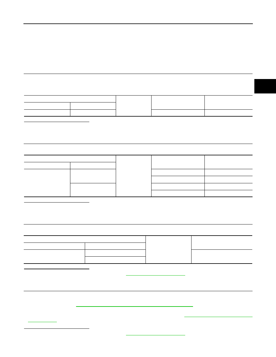
A/T assembly vehicle side harness connector
Ground
Condition
Voltage (Approx.)
Connector
Terminal
F51
2
Always
Battery voltage
A/T assembly vehicle side harness connector
Ground
Condition
Voltage (Approx.)
Connector
Terminal
F51
1
Turn ignition switch ON
Battery voltage
Turn ignition switch OFF
0 V
6
Turn ignition switch ON
Battery voltage
Turn ignition switch OFF
0 V
A/T assembly vehicle side harness connector
Ground
Continuity
Connector
Terminal
F51
5
Existed
10
TM-302
< DTC/CIRCUIT DIAGNOSIS >
[7AT: RE7R01B (VK50VE)]
MAIN POWER SUPPLY AND GROUND CIRCUIT
5.
CHECK HARNESS BETWEEN IPDM E/R AND A/T ASSEMBLY (PART 1)
1.
Turn ignition switch OFF.
2.
Disconnect IPDM E/R connector.
3.
Check continuity between IPDM E/R vehicle side harness connector terminal and A/T assembly vehicle
side harness connector terminals.
Is the inspection result normal?
YES
>> GO TO 6.
NO
>> Repair or replace damaged parts.
6.
CHECK HARNESS BETWEEN IPDM E/R AND A/T ASSEMBLY (PART 2)
Check continuity between A/T assembly vehicle side harness connector terminal and ground.
Is the inspection result normal?
YES
>> GO TO 7.
NO
>> Repair or replace damaged parts.
7.
DETECT MALFUNCTIONING ITEM
Check the following.
• Harness for short or open between ignition switch and IPDM E/R. Refer to
PG-81, "Wiring Diagram - IGNI-
• Ignition switch
• 10A fuse (No.43, located in the IPDM E/R). Refer to
PG-158, "Fuse, Connector and Terminal Arrangement"
.
• IPDM E/R
Is the inspection result normal?
YES
>> Check intermittent incident. Refer to
GI-36, "Intermittent Incident"
.
NO
>> Repair or replace damaged parts.
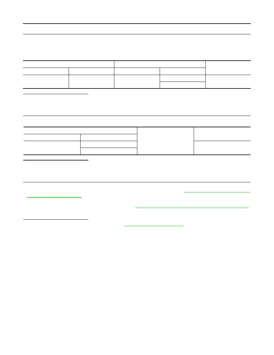
IPDM E/R vehicle side harness connector
A/T assembly vehicle side harness connector
Continuity
Connector
Terminal
Connector
Terminal
E7
58
F51
1
Existed
6
A/T assembly vehicle side harness connector
Ground
Continuity
Connector
Terminal
E51
1
Not existed
6
Нет комментариевНе стесняйтесь поделиться с нами вашим ценным мнением.
Текст