Infiniti FX35, FX50 (S51). Manual — part 64
AV
DIAGNOSIS SYSTEM (AV CONTROL UNIT)
AV-29
< SYSTEM DESCRIPTION >
[WITHOUT NAVIGATION]
C
D
E
F
G
H
I
J
K
L
M
B
A
O
P
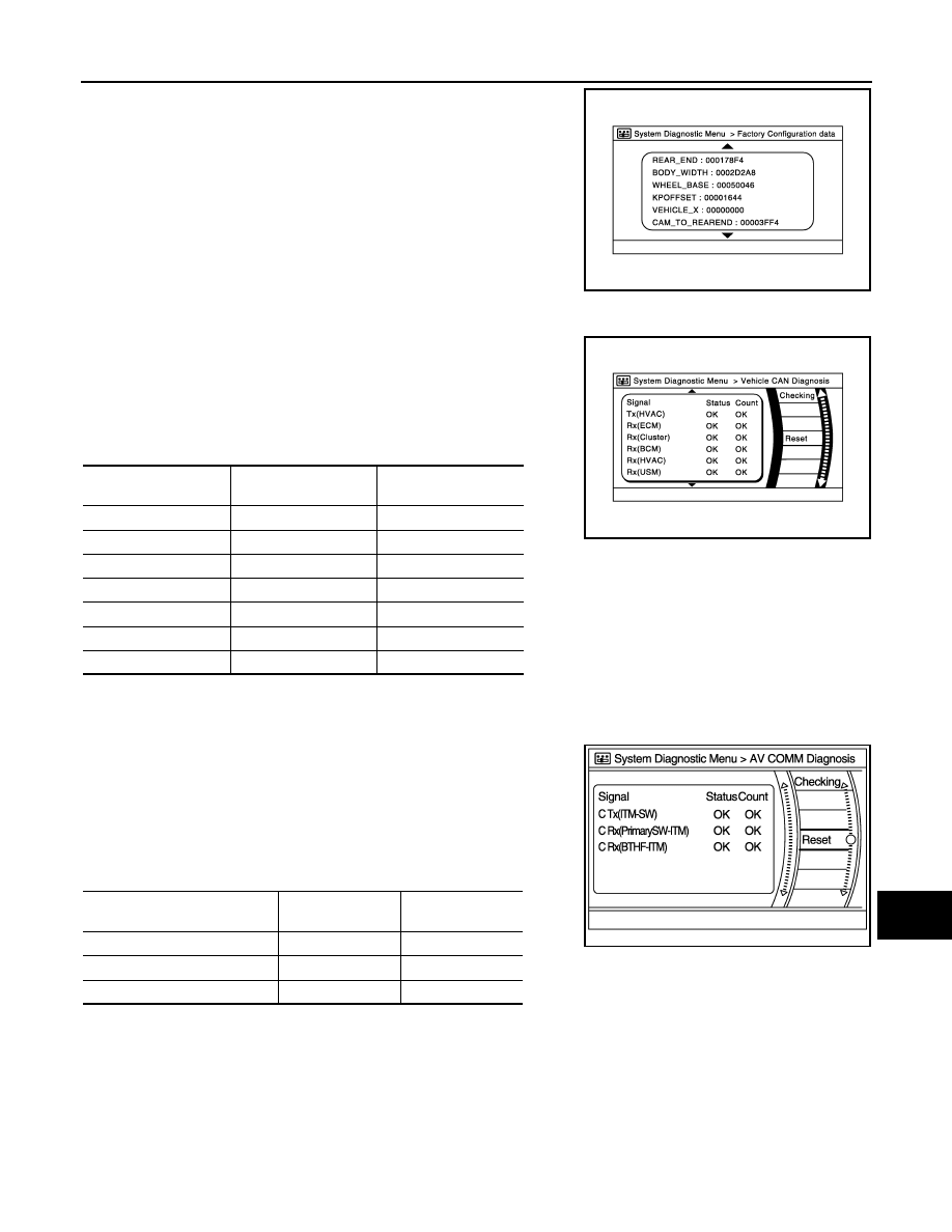
• Configuration stored in the AV control unit can be checked.
Vehicle CAN Diagnosis
• CAN communication status and error counter is displayed.
• The error counter displays “OK” if any malfunction was not
detected in the past and displays “0” if a malfunction is detected. It
increases by 1 if the condition is normal at the next ignition switch
ON cycle. The upper limit of the counter is 39.
• The error counter is erased if “Reset” is pressed.
NOTE:
“???” indicates UNKWN.
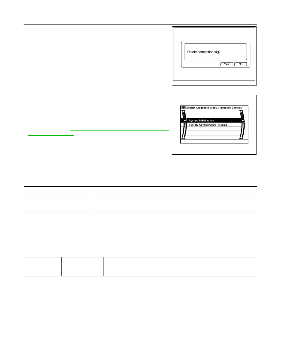
AV COMM Diagnosis
• Displays the communication status between AV control unit (mas-
ter unit) and each unit.
• The error counter displays “OK” if any malfunction was not
detected in the past and displays “0” if a malfunction is detected. It
increases by 1 if the condition is normal at the next ignition switch
ON cycle. The upper limit of the counter is 39.
• The error counter is erased if “Reset” is pressed.
NOTE:
“???” indicates UNKWN.
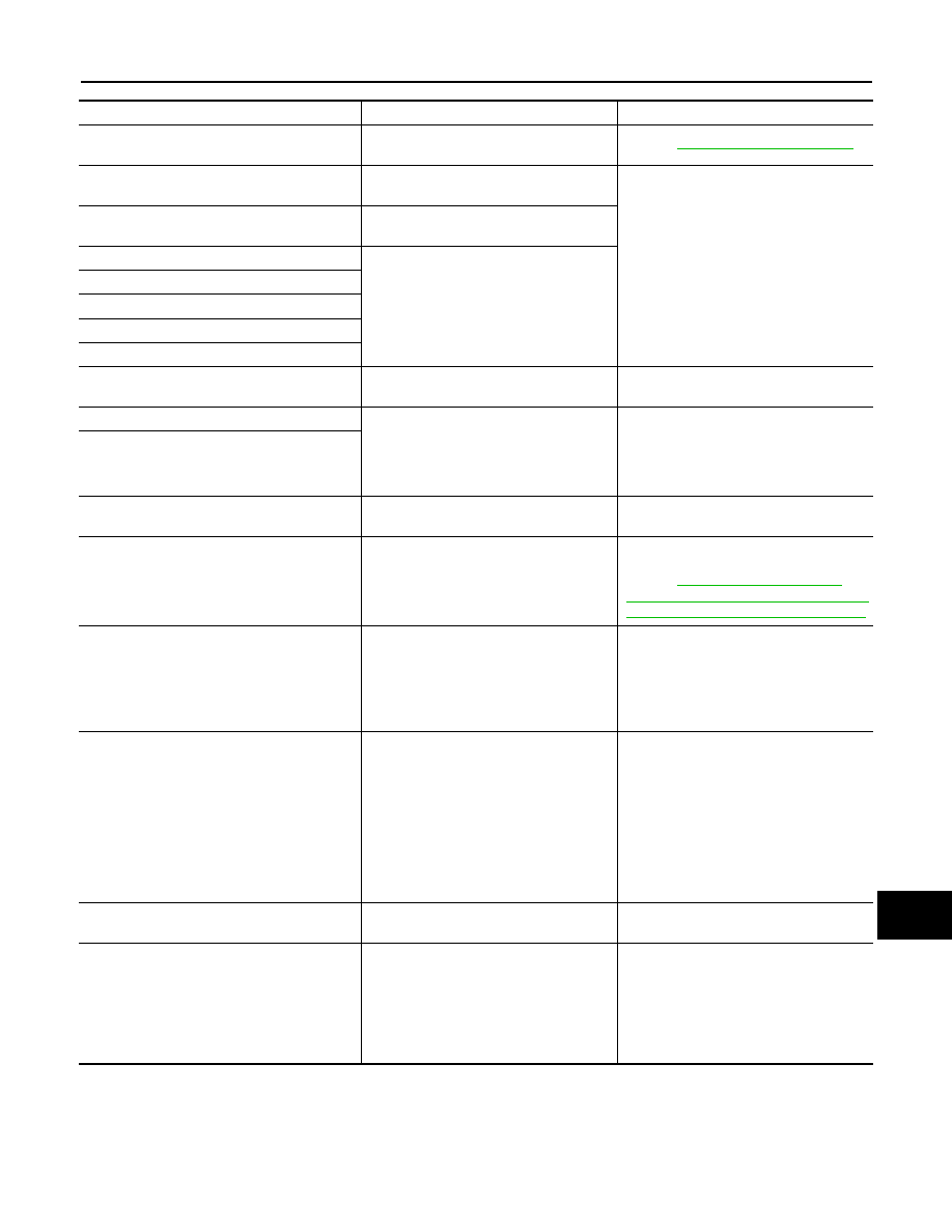
Delete Unit Connection Log
JSNIA2234ZZ
Items
Display (Current)
Malfunction counter
(Past)
Tx(HVAC)
OK / ???
OK / 0 – 39
Rx(ECM)
OK / ???
OK / 0 – 39
Rx(Cluster)
OK / ???
OK / 0 – 39
Rx(BCM)
OK / ???
OK / 0 – 39
Rx(HVAC)
OK / ???
OK / 0 – 39
Rx(USM)
OK / ???
OK / 0 – 39
Rx(STRG)
OK / ???
OK / 0 – 39
JSNIA2235ZZ
Items
Status
(Current)
Counter
(Past)
C Tx(ITM-PrimarySW)
OK / ???
OK / 0 – 39
C Rx(PrimarySW-ITM)
OK / ???
OK / 0 – 39
C Rx(BTHF-ITM)
OK / ???
OK / 0 – 39
JSNIA2505ZZ
AV-30
< SYSTEM DESCRIPTION >
[WITHOUT NAVIGATION]
DIAGNOSIS SYSTEM (AV CONTROL UNIT)
Deletes any unit connection records and error records from the AV
control unit memory. (Clear the records of the unit that has been
removed.)
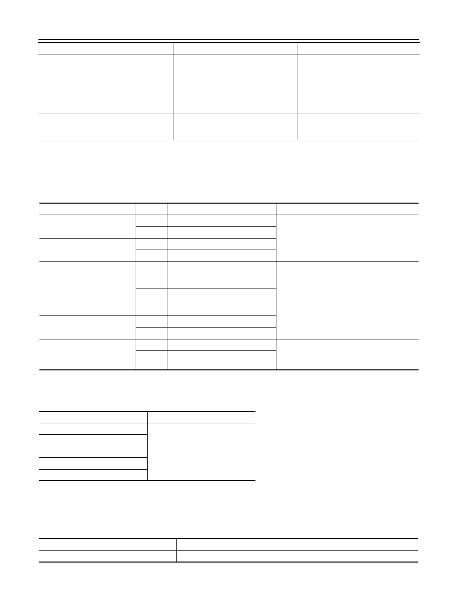
Initialize Settings
“User Data Initialization” and “Accessory Number Initialization” are
possible.
CAUTION:
• Never perform Accessory Number Initialization except when
configuration is unsuccessful.
• Accessory Number Initialization requires configuration. For
details, refer to
AV-79, "CONFIGURATION (AV CONTROL
CONSULT - III Function (MULTI AV)
INFOID:0000000005527812
CONSULT-III FUNCTIONS
CONSULT-III performs the following functions via the communication with the AV control unit.
AV COMMUNICATION
When “AV communication” of “CAN Diag Support Monitor” is selected, the following function will be performed.
ECU IDENTIFICATION
The part number of AV control unit is displayed.
SELF DIAGNOSIS RESULT
• In CONSULT-III self-diagnosis, self-diagnosis results and error history are displayed collectively.
• The current malfunction indicates “CRNT”. The past malfunction indicates “PAST”.
• The timing is displayed as “0” if any of the error codes [U1000], [U1010], [U1300] and [U1310] is detected.
The counter increases by 1 if the condition is normal at the next ignition switch ON cycle.
Self-diagnosis Results Display Item
JSNIA0154GB
JSNIA2237ZZ
Diagnosis mode
Description
Ecu Identification
The part number of AV control unit can be checked.
Self Diagnostic Result
Performs a diagnosis on the AV control unit and a connection diagnosis for the communication
circuit of the Multi AV system, and displays the current and past malfunctions collectively.
Data Monitor
The diagnosis of vehicle signal that is input to the AV control unit can be performed.
Work Support
Steering angle sensor can be adjusted.
Configuration
• Read and save the vehicle specification.
• Write the vehicle specification when replacing AV control unit.
AV communication
AV&NAVI C/U
Displays the communication status from AV control unit to each unit as well as the error
counter.
AUDIO
Displays the AV control unit communication status and the error counter.
AV
DIAGNOSIS SYSTEM (AV CONTROL UNIT)
AV-31
< SYSTEM DESCRIPTION >
[WITHOUT NAVIGATION]
C
D
E
F
G
H
I
J
K
L
M
B
A
O
P
Error item
Description
Possible malfunction factor/Action to take
CAN COMM CIRCUIT [U1000]
CAN communication malfunction is de-
tected.
Refer to
.
CONTROL UNIT (CAN) [U1010]
CAN initial diagnosis malfunction is de-
tected.
Replace the AV control unit if the malfunc-
tion occurs constantly.
CONTROL UNIT (AV) [U1310]
AV communication circuit initial diagnosis
malfunction is detected.
Cont Unit [U1200]
AV control unit malfunction is detected.
CAN CONT [U1216]
SUB CPU CONN [U1228]
iPod CERTIFICATION [U1229]
Built-in AUDIO CONN [U122E]
USB CONTROLLER [U1225]
USB connection malfunction is detected.
Check that the connection to the USB con-
nector is normal.
DSP CONN [U121D]
AV control unit malfunction is detected.
• If a disc can be played, then there is a
possibility of the detection of a tempo-
rary malfunction.
• Replace the AV control unit if the mal-
function occurs constantly.
DSP COMM [U121E]
CONFIG UNFINISH [U122A]
The writing of configuration data is incom-
plete.
Write configuration data with CONSULT-
III.
ST ANGLE SEN CALIB [U1232]
Predictive course line center position ad-
justment of the steering angle sensor is in-
complete.
Adjust the predictive course line center
position of the steering angle sensor.
Refer to
STEERING ANGLE SENSOR NEUTRAL
POSITION : Special Repair Requirement"
FRONT DISP CONN [U1243]
When either one of the following items is
detected:
• Front display unit power supply and
ground circuits malfunction is detected.
• Communication circuits between AV
control unit and front display unit.
• Front display unit power supply and
ground circuits.
• Communication circuits between AV
control unit and front display unit.
SAT CONN [U1255]
When either one of the following items is
detected:
• satellite radio tuner power supply and
ground circuit malfunction is detected.
• malfunction is detected in communica-
tion circuits between AV control unit and
satellite radio tuner.
• malfunction is detected in request sig-
nal circuit between AV control unit and
satellite radio tuner.
• Satellite radio tuner power supply and
ground circuit.
• Communication circuit between AV con-
trol unit and satellite radio tuner.
• Request signal circuit between AV con-
trol unit and satellite radio tuner.
USB OVERCURRENT [U1263]
Detection of overcurrent in USB connec-
tor.
Check USB harness between the AV con-
trol unit and USB connector.
• AV COMM CIRCUIT [U1300]
• SWITCH CONN [U1240]
When either one of the following items is
detected:
• multifunction switch power supply and
ground circuits are malfunctioning.
• AV communication circuits between AV
control unit and multifunction switch are
malfunctioning.
• Multifunction switch power supply and
ground circuits.
• AV communication circuits between AV
control unit and multifunction switch.
AV-32
< SYSTEM DESCRIPTION >
[WITHOUT NAVIGATION]
DIAGNOSIS SYSTEM (AV CONTROL UNIT)
DATA MONITOR
ALL SIGNALS
• Displays the status of the following vehicle signals inputted into the AV control unit.
• For each signal, actual signal can be compared with the condition recognized on the system.
SELECTION FROM MENU
Allows the technician to select which vehicle signals should be displayed and displays the status of the
selected vehicle signals.
WORK SUPPORT
Adjusts the neutral position of the steering angle sensor.
CAUTION:
For vehicles with VDC, adjust the steering angle sensor neutral position on the ABS actuator control
unit side.
• AV COMM CIRCUIT [U1300]
• HAND FREE CONN [U1256]
When either one of the following items is
detected:
• TEL adapter unit power supply and
ground circuits are malfunctioning.
• AV communication circuits between AV
control unit and TEL adapter unit are
malfunctioning.
• TEL adapter unit power supply and
ground circuits.
• AV communication circuits between AV
control unit and TEL adapter unit.
• AV COMM CIRCUIT [U1300]
• SWITCH CONN [U1240]
• HAND FREE CONN [U1256]
Malfunction is detected in AV communica-
tion circuits between AV control unit and
multifunction switch.
AV communication circuits between AV
control unit and multifunction switch.
Error item
Description
Possible malfunction factor/Action to take
Display Item
Display
Vehicle status
Remarks
VHCL SPD SIG
On
Vehicle speed >0 km/h (0 MPH)
Changes in indication may be delayed. This is
normal.
Off
Vehicle speed =0 km/h (0 MPH)
PKB SIG
On
Parking brake is applied.
Off
Parking brake is released.
ILLUM SIG
On
Block the light beam from the auto
light optical sensor when the light
SW is ON.
—
Off
Expose the auto light optical sensor
to light when the light SW is OFF or
ON.
IGN SIG
On
Ignition switch ON
Off
Ignition switch in ACC position
REV SIG
On
Selector lever in R position
Changes in indication may be delayed. This is
normal.
Off
Selector lever in any position other
than R
Item to be selected
Description
VHCL SPD SIG
The same as when “ALL SIGNALS”
is selected.
PKB SIG
ILLUM SIG
IGN SIG
REV SIG
Item
Description
ST ANGLE SENSOR ADJUSTMENT
Adjusts the neutral position of the steering angle sensor.
Нет комментариевНе стесняйтесь поделиться с нами вашим ценным мнением.
Текст