Infiniti FX35, FX50 (S51). Manual — part 63
AV
DIAGNOSIS SYSTEM (AV CONTROL UNIT)
AV-25
< SYSTEM DESCRIPTION >
[WITHOUT NAVIGATION]
C
D
E
F
G
H
I
J
K
L
M
B
A
O
P
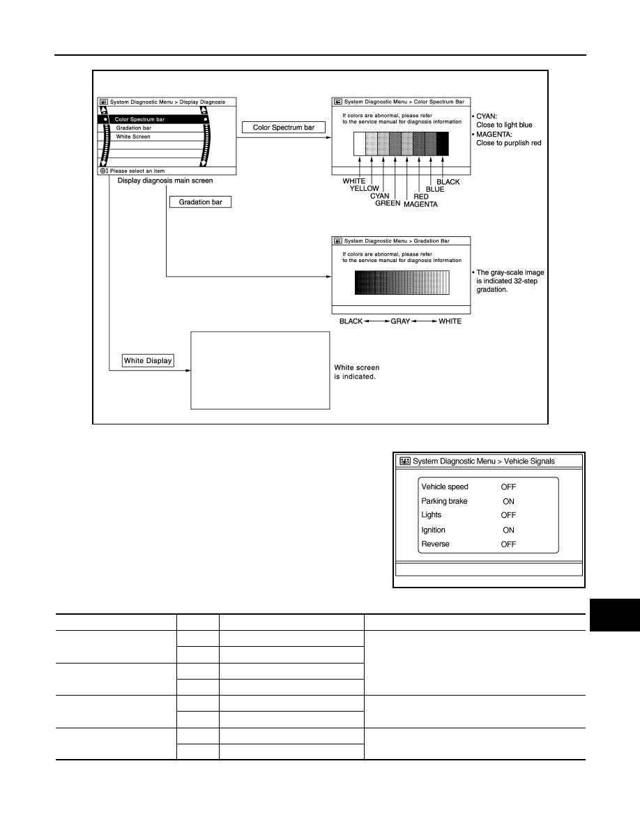
Display Diagnosis
Vehicle Signals
A comparison check can be made of each actual vehicle signal and
the signals recognized by the system.
JSNIA2233GB
JSNIA0149GB
Diagnosis item
Display
Vehicle status
Remarks
Vehicle speed
ON
Vehicle speed > 0 km/h (0 MPH)
Changes in indication may be delayed. This is normal.
OFF
Vehicle speed = 0 km/h (0 MPH)
Parking brake
ON
Parking brake is applied.
OFF
Parking brake is released.
Lights
ON
Light switch ON
—
OFF
Light switch OFF
Ignition
ON
Ignition switch ON
—
OFF
Ignition switch in ACC position

AV-26
< SYSTEM DESCRIPTION >
[WITHOUT NAVIGATION]
DIAGNOSIS SYSTEM (AV CONTROL UNIT)
Speaker Test
Select “Speaker Test” to display the Speaker Diagnosis screen.
Press “Start” to generate a test tone in a speaker. Press “Start” again
to generate a test tone in the next speaker. Press “End” to stop the
test tones.
Climate Control
Refer to “HEATER & AIR CONDITIONING CONTROL SYSTEM” for details.
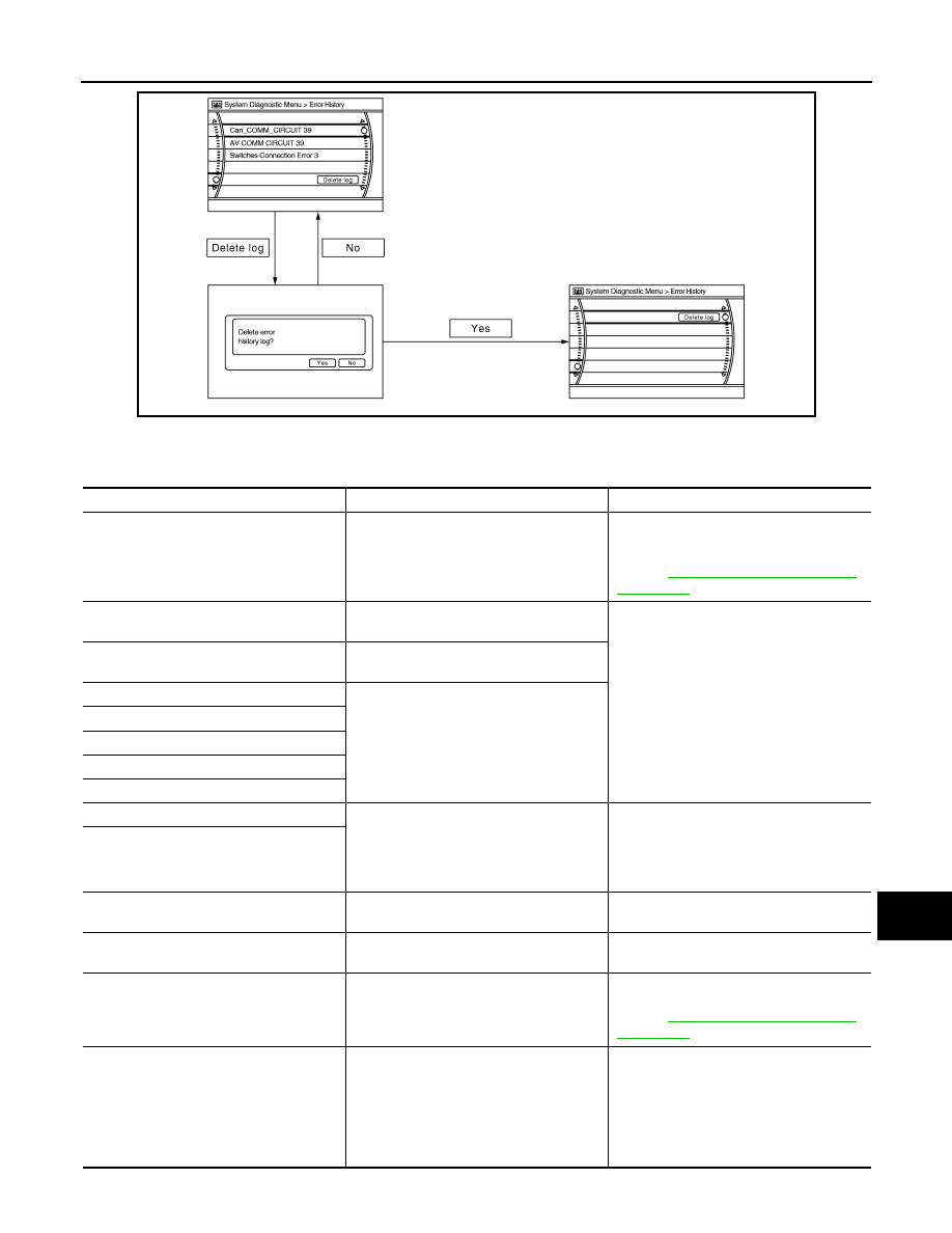
Error History
The self-diagnosis results are judged depending on whether any error occurs from when “Self-diagnosis” is
selected until the self-diagnosis results are displayed.
However, the diagnosis results are judged normal if an error has occurred before the ignition switch is turned
ON and then no error has occurred until the self-diagnosis start. Check the “Error Record” to detect any error
that may have occurred before the self-diagnosis start because of this situation.
The frequency of occurrence is displayed in a count up manner. The actual count up method differs depending
on the error item.
Count up method A
• The counter resets to 0 if an error occurs when ignition switch is turned ON. The counter increases by 1 if
the condition is normal at a next ignition ON cycle.
• The counter upper limit is 39. Any counts exceeding 39 are ignored.“ The counter can be reset (no error
record display) with the “Delete log” switch or CONSULT-III.
Count up method B
• The counter increases by 1 if an error occurs when ignition switch is ON. The counter will not decrease even
if the condition is normal at the next ignition ON cycle.
• The counter upper limit is 50. Any counts exceeding 50 are ignored. “ The counter can be reset (no error
record display) with the “Delete log” switch or CONSULT-III.
Reverse
ON
Shift the selector lever to “R” posi-
tion
Changes in indication may be delayed. This is normal.
OFF
Shift the selector lever other than
“R” position
Diagnosis item
Display
Vehicle status
Remarks
JSNIA0150GB
Display type of occur-
rence frequency
Error history display item
Count up method A
CAN communication line, control unit (CAN), AV communication line, control unit (AV)
Count up method B
Other than the above
AV
DIAGNOSIS SYSTEM (AV CONTROL UNIT)
AV-27
< SYSTEM DESCRIPTION >
[WITHOUT NAVIGATION]
C
D
E
F
G
H
I
J
K
L
M
B
A
O
P
Error item
Some error items may be displayed simultaneously according to the cause. If some error items are displayed
simultaneously, the detection of the cause can be performed by the combination of display items
JSNIA0151GB
Error item
Description
Possible malfunction factor/Action to take
CAN COMM CIRCUIT
CAN communication malfunction is detect-
ed.
Perform diagnosis with CONSULT-III, and
then repair the malfunctioning parts accord-
ing to the diagnosis results.
Refer to
AV-30, "CONSULT - III Function
CONTROL UNIT (CAN)
CAN initial diagnosis malfunction is detect-
ed.
Replace the AV control unit if the malfunc-
tion occurs constantly.
CONTROL UNIT (AV)
AV communication circuit initial diagnosis
malfunction is detected.
FLASH-ROM Error Of Control Unit
AV control unit malfunction is detected.
CAN Controller Memory Error
Sub CPU Connection Error
iPod authentification chip error
Audio connection error
DSP Connection Error
AV control unit malfunction is detected.
• If a disc can be played, then there is a
possibility of the detection of a temporary
malfunction.
• Replace the AV control unit if the mal-
function occurs constantly.
DSP Communication Error
Unfinished configuration
The writing of configuration data is incom-
plete.
Write configuration data with CONSULT-III.
USB Controller Communication Error
USB connection malfunction is detected.
Check that the connection to the USB con-
nector is normal.
Steer. Angle Sensor Calibration
Predictive course line center position ad-
justment of the steering angle sensor is in-
complete.
Adjust the predictive course line center po-
sition of the steering angle sensor.
Refer to
AV-30, "CONSULT - III Function
Front Display Connection Error
When either one of the following items is
detected:
• front display unit power supply and
ground circuits malfunction is detected.
• malfunction is detected in communica-
tion circuits between AV control unit and
front display unit.
• Front display unit power supply and
ground circuits.
• Communication circuits between AV con-
trol unit and front display unit.
AV-28
< SYSTEM DESCRIPTION >
[WITHOUT NAVIGATION]
DIAGNOSIS SYSTEM (AV CONTROL UNIT)
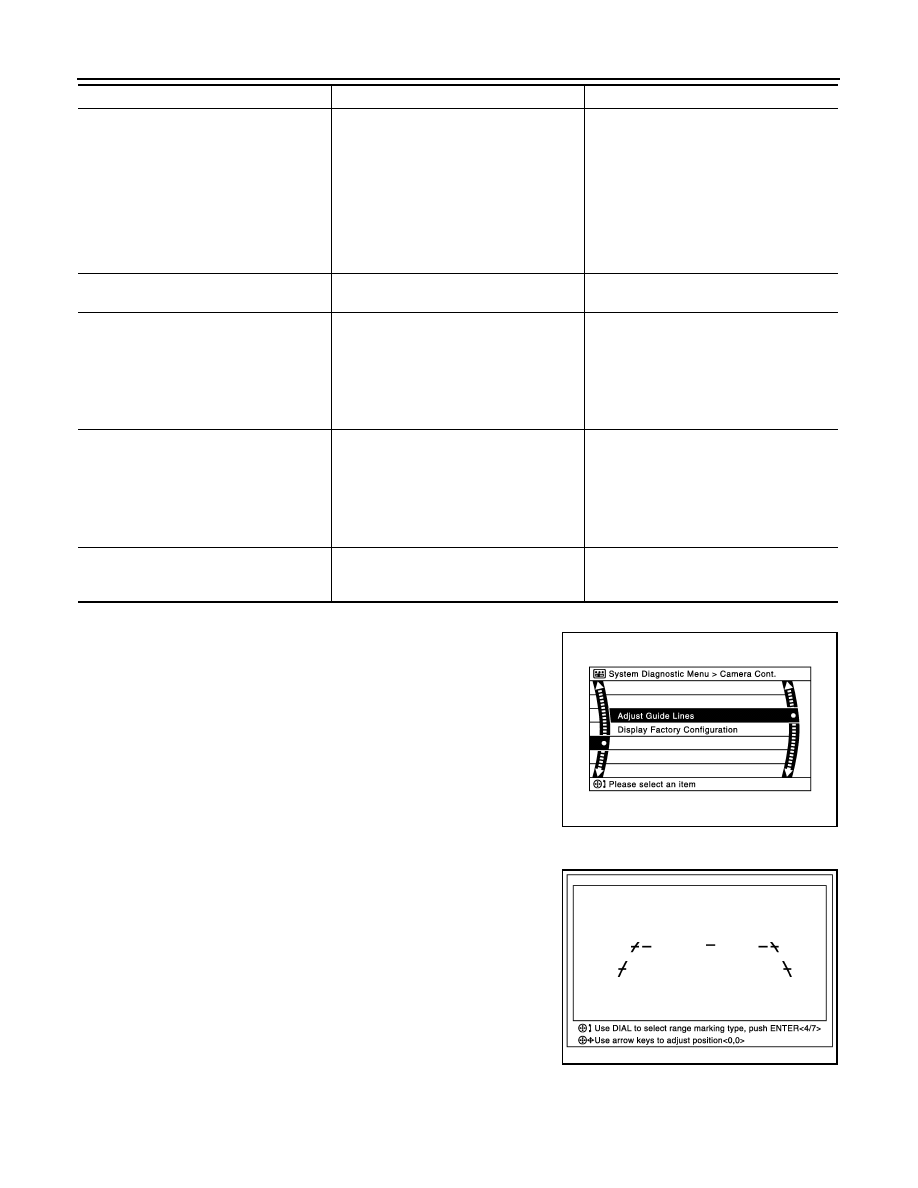
Camera Cont.
The two functions of “Correct Draw Line of Rear view Cam”, “Con-
firm Configuration” are available.
Adjust Offset of Rear view Camera
• Use this mode to adjust the guide line display position of the rear
view monitor if necessary after removing the rear view monitor
camera.
Factory Configuration Confirmation
XM Connection Error
When either one of the following items is
detected:
• satellite radio tuner power supply and
ground circuit malfunction is detected.
• malfunction is detected in communica-
tion circuits between AV control unit and
satellite radio tuner.
• malfunction is detected in request signal
circuit between AV control unit and satel-
lite radio tuner.
• Satellite radio tuner power supply and
ground circuit.
• Communication circuit between AV con-
trol unit and satellite radio tuner.
• Request signal circuit between AV con-
trol unit and satellite radio tuner.
USB electric current Error
Detection of overcurrent in USB connector.
Check USB harness between the AV con-
trol unit and USB connector.
• AV COMM CIRCUIT
• Switches Connection Error
When either one of the following items is
detected:
• multifunction switch power supply and
ground circuits are malfunctioning.
• AV communication circuits between AV
control unit and multifunction switch are
malfunctioning.
• Multifunction switch power supply and
ground circuits.
• AV communication circuits between AV
control unit and multifunction switch.
• AV COMM CIRCUIT
• H/F Unit Connection Error
When either one of the following items is
detected:
• TEL adapter unit power supply and
ground circuits are malfunctioning.
• AV communication circuits between AV
control unit and TEL adapter unit are
malfunctioning.
• TEL adapter unit power supply and
ground circuits.
• AV communication circuits between AV
control unit and TEL adapter unit.
• AV COMM CIRCUIT
• Switches Connection Error
• H/F Unit Connection Error
Malfunction is detected in AV communica-
tion circuits between AV control unit and
multifunction switch.
AV communication circuits between AV
control unit and multifunction switch.
Error item
Description
Possible malfunction factor/Action to take
JSNIA2230ZZ
JSNIA2231ZZ
Нет комментариевНе стесняйтесь поделиться с нами вашим ценным мнением.
Текст