Infiniti I35 (A33). Manual — part 200
TER-
MINAL
NO.
WIRE
COLOR
ITEM
CONDITION
DATA (DC Voltage)
36
LG
Cooling fan relay
(HIGH)
[Engine is running]
I
Cooling fan is operating at high speed.
0 - 1.0V
[Engine is running]
I
Cooling fan is not operating.
BATTERY VOLTAGE
(11 - 14V)
38
W/B
ECM relay
(Self shut-off)
[Engine is running]
[Ignition switch ON]
I
For a few seconds after turning ignition switch
OFF
0 - 1.5V
[Ignition switch ON]
I
A few seconds after turning ignition switch OFF
BATTERY VOLTAGE
(11 - 14V)
39
OR/L
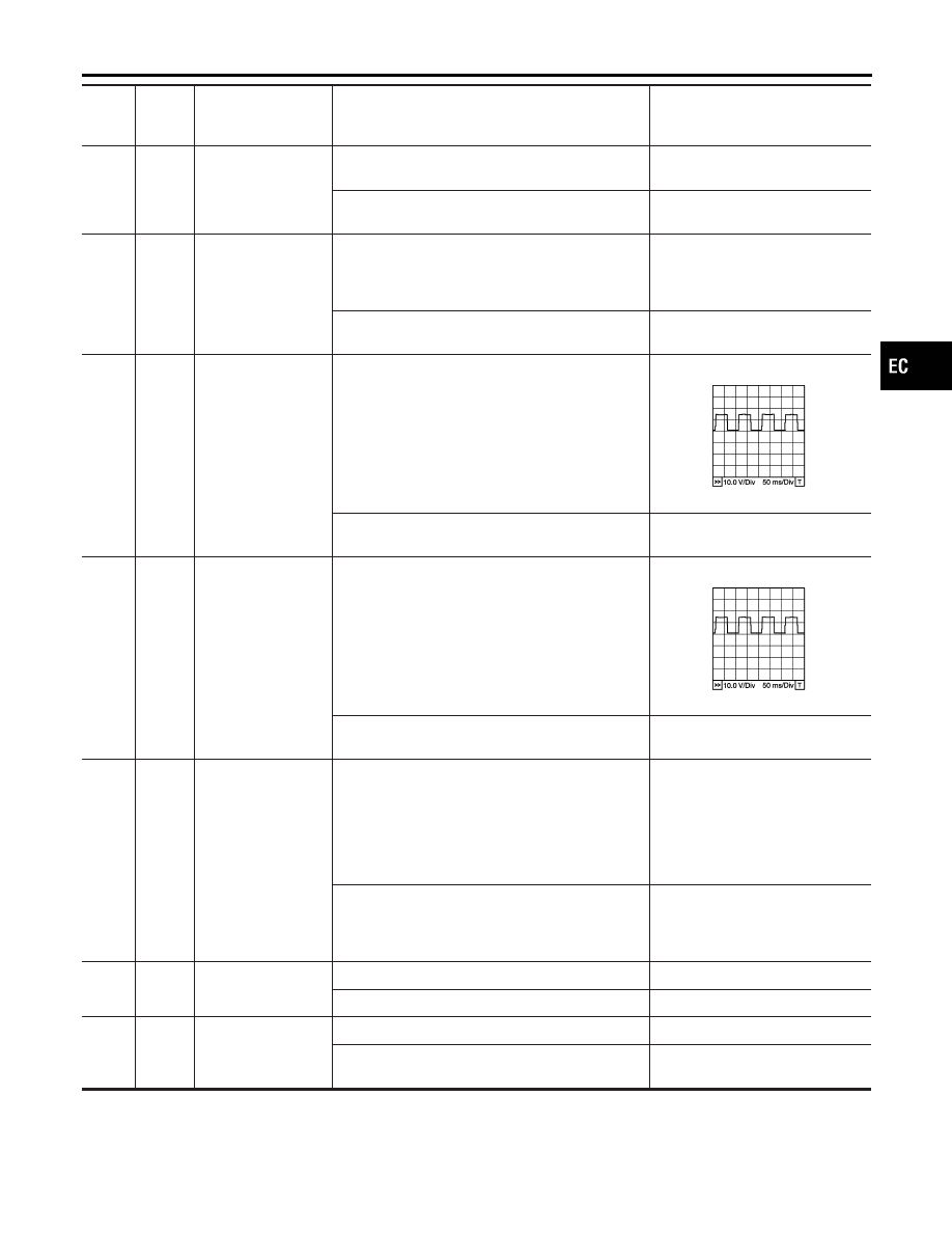
Heated oxygen sen-
sor 1 heater (bank 1)
[Engine is running]
I
Warm-up condition
I
Engine speed is below 3,600 rpm.
Approximately 7V
★
PBIB0519E
[Engine is running]
I
Engine speed is above 3,600 rpm.
BATTERY VOLTAGE
(11 - 14V)
40
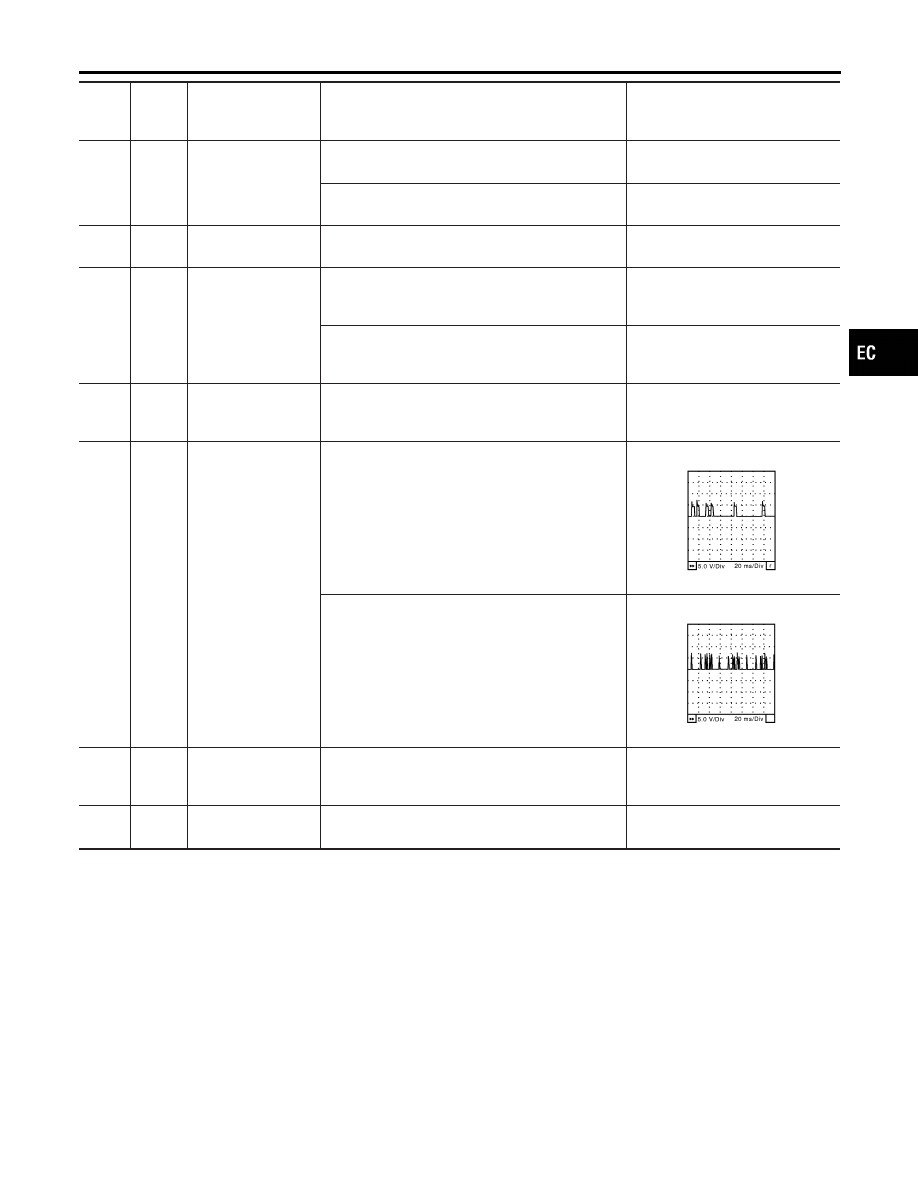
R/L
Heated oxygen sen-
sor 1 heater (bank 2)
[Engine is running]
I
Warm-up condition
I
Engine speed is below 3,600 rpm.
Approximately 7V
★
PBIB0519E
[Engine is running]
I
Engine speed is above 3,600 rpm.
BATTERY VOLTAGE
(11 - 14V)
41
P/B
Heated oxygen sen-
sor 2 heater (bank 1)
[Engine is running]
I
Engine speed is below 3,600 rpm after the fol-
lowing conditions are met.
–
Engine: after warming up
–
Keeping engine speed between 3,500 and
4,000 rpm for 1 minute and at idle for 1 minute
under no load
0 - 0.5V
[Ignition switch ON]
I
Engine stopped
[Engine is running]
I
Engine speed is above 3,600 rpm.
BATTERY VOLTAGE
(11 - 14V)
42
BR/W
Start signal
[Ignition switch ON]
Approximately 0V
[Ignition switch START]
9 - 12V
43
R
Ignition switch
[Ignition switch OFF]
0V
[Ignition switch “ON]
BATTERY VOLTAGE
(11 - 14V)
GI
MA
EM
LC
FE
AT
AX
SU
BR
ST
RS
BT
HA
SC
EL
IDX
TROUBLE DIAGNOSIS — GENERAL DESCRIPTION
ECM Terminals and Reference Value (Cont’d)
EC-141

TER-
MINAL
NO.
WIRE
COLOR
ITEM
CONDITION
DATA (DC Voltage)
44
G/OR
PNP switch
[Ignition switch ON]
I
General position is P or N.
Approximately 0V
[Ignition switch ON]
I
Except the above gear position
BATTERY VOLTAGE
(11 - 14V)
45
G/B
Air conditioner switch
signal
[Engine is running]
I
Both A/C switch and blower switch are ON.
Approximately 0V
[Engine is running]
I
A/C switch is OFF.
BATTERY VOLTAGE
(11 - 14V)
47
R/L
Heated oxygen sen-
sor 2 heater (bank 2)
[Engine is running]
I
Engine speed is below 3,600 rpm after the fol-
lowing conditions are met.
–
Engine: after warming up
–
Keeping engine speed between 3,500 and
4,000 rpm for 1 minute and at idle for 1 minute
under no load
0 - 0.5V
[Ignition switch ON]
I
Engine stopped
[Engine is running]
I
Engine speed is above 3,600 rpm.
BATTERY VOLTAGE
(11 - 14V)
48
B
ECM ground
[Engine is running]
I
Idle speed
Engine ground
50
G/Y
ASCD steering
switch
[Ignition switch ON]
I
ASCD steering switch is OFF.
Approximately 4.0V
[Ignition switch ON]
I
MAIN switch: Pressed
Approximately 0V
[Ignition switch ON]
I
CANCEL switch: Pressed
Approximately 1.0V
[Ignition switch ON]
I
RESUME/ACCEL switch: Pressed
Approximately 3.0V
[Ignition switch ON]
I
SET/COAST switch: Pressed
Approximately 2.0V
51
W/G
Electrical load signal
[Engine is running]
I
Rear window defogger: ON
I
Hi-beam headlamp: ON
BATTERY VOLTAGE
(11 - 14V)
[Engine is running]
I
Electrical load: OFF
0V
55
R/G
Stop lamp switch
[Ignition switch ON]
Brake pedal is depressed.
BATTERY VOLTAGE
(11 - 14V)
[Ignition switch ON]
Brake pedal is released.
Approximately 0V
57
B
ECM ground
[Engine is running]
I
Idle speed
Engine ground
58
B
Sensor ground
[Engine is running]
I
Warm-up condition
I
Idle speed
Approximately 0V
TROUBLE DIAGNOSIS — GENERAL DESCRIPTION
ECM Terminals and Reference Value (Cont’d)
EC-142
TER-
MINAL
NO.
WIRE
COLOR
ITEM
CONDITION
DATA (DC Voltage)
59
G/B
ASCD brake switch
[Ignition switch ON]
I
Brake pedal is depressed.
0V
[Ignition switch ON]
I
Brake pedal is released.
BATTERY VOLTAGE
(11 - 14V)
60
W
EVAP control system
pressure sensor
[Ignition switch ON]
Approximately 3.4V
62
W
Mass air flow sensor
[Engine is running]
I
Warm-up condition
I
Idle speed
1.1 - 1.5V
[Engine is running]
I
Warm-up condition
I
Engine speed is 2,500 rpm.
1.7 - 2.4V
64
OR
Accelerator pedal
position sensor 2
power supply
[Ignition switch ON]
Approximately 2.5V
65
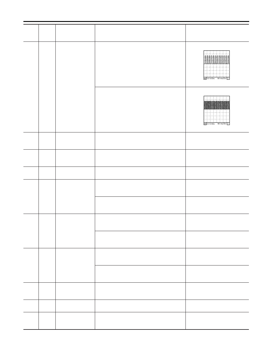
Y
Camshaft position
sensor (PHASE)
(bank 1)
[Engine is running]
I
Warm-up condition
I
Idle speed
NOTE:
The pulse cycle changes depending on rpm at idle.
1.0 - 4.0V
★
SEC033D
[Engine is running]
I
Engine speed is 2,000 rpm.
1.0 - 4.0V
★
SEC034D
66
Y/G
Mass air flow sensor
(Intake air tempera-
ture sensor)
[Engine is running]
Approximately 0 - 4.8V
Output voltage varies with intake
air temperature.
67
W/L
Power supply for
ECM (Back-up)
[Ignition switch OFF]
BATTERY VOLTAGE
(11 - 14V)
GI
MA
EM
LC
FE
AT
AX
SU
BR
ST
RS
BT
HA
SC
EL
IDX
TROUBLE DIAGNOSIS — GENERAL DESCRIPTION
ECM Terminals and Reference Value (Cont’d)
EC-143
TER-
MINAL
NO.
WIRE
COLOR
ITEM
CONDITION
DATA (DC Voltage)
68
P/L
Vehicle speed sensor
[Engine is running]
I
Jack-up front wheels
I
In 1st gear position
I
10 km/h (6 MPH)
Approximately 2.5V
★
SEC039D
[Engine is running]
I
Jack-up front wheels
I
In 2nd gear position
I
30 km/h (19 MPH)
Approximately 2.5V
★
SEC040D
69
G
Fuel level sensor
[Ignition switch ON]
Approximately 0 - 4.8V
Output voltage varies with fuel
level.
70
B/P
Accelerator pedal
position sensor 2
ground
[Ignition switch ON]
Approximately 0V
71
W
Knock sensor
[Engine is running]
I
Idle speed
Approximately 2.5V
72
W
Accelerator pedal
position sensor signal
output
[Engine is running]
I
Warm-up condition
I
Accelerator pedal released
Approximately 0.6V
[Ignition switch ON]
I
Engine stopped
I
Accelerator pedal fully depressed
Approximately 4.0V
73
W
Accelerator pedal
position sensor 1
[Ignition switch ON]
I
Engine stopped
I
Accelerator pedal released
0.41 - 0.71V
[Ignition switch ON]
I
Engine stopped
I
Accelerator pedal fully depressed
More than 3.7V
74
W/B
Accelerator pedal
position sensor 2
[Ignition switch ON]
I
Engine stopped
I
Accelerator pedal released
0.08 - 0.48V
[Ignition switch ON]
I
Engine stopped
I
Accelerator pedal fully depressed
More than 1.8V
75
P/B
Fuel tank tempera-
ture sensor
[Engine is running]
Approximately 0 - 4.8V
Output voltage varies with fuel
tank temperature.
78
B
Fuel level sensor
ground
[Engine is running]
I
Idle speed
Approximately 0V
80
B
Mass air flow sensor
ground
[Engine is running]
I
Warm-up condition
I
Idle speed
Approximately 0V
TROUBLE DIAGNOSIS — GENERAL DESCRIPTION
ECM Terminals and Reference Value (Cont’d)
EC-144
Нет комментариевНе стесняйтесь поделиться с нами вашим ценным мнением.
Текст