Infiniti I35 (A33). Manual — part 198
MONITOR ITEM
CONDITION
SPECIFICATION
VENT CONT/V
I
Ignition switch: ON
OFF
HO2S1 HTR (B1)
HO2S1 HTR (B2)
I
Engine: After warming up
I
Engine speed: Below 3,600 rpm
ON
I
Engine speed: Above 3,600 rpm
OFF
HO2S2 HTR (B1)
HO2S2 HTR (B2)
I
Ignition switch: ON (Engine stopped)
I
Engine speed: Above 3,600 rpm
OFF
I
Engine speed: Below 3,600 rpm after the following conditions are met.
I
After warming up
I
After keeping the engine speed between 3,500 and 4,000 rpm for 1
minute and at idle for 1 minute under no load
ON
VC/V BYPASS/V
Ignition switch: ON
OFF
CAL/LD VALUE
I
Engine: After warming up
I
Air conditioner switch: OFF
I
Shift lever: N
I
No-load
Idle
10 - 35%
2,500 rpm
10 - 35%
BRAKE SW
I
Ignition switch: ON
Brake pedal: Released
OFF
Brake pedal: Slightly depressed
ON
MASS AIRFLOW
I
Engine: After warming up
I
Air conditioner switch: OFF
I
Shift lever: N
I
No-load
Idle
2.0 - 6.0 g·m/s
2,500 rpm
7.0 - 20.0 g·m/s
ABSOL PRES/SE
I
Ignition switch: ON
Approx. 4.4V
VIAS S/V
I
Engine: After warming up
1,800 - 3,600 rpm
ON
Except above conditions
OFF
TRVL AFTER MIL
Ignition switch: ON
Vehicle has traveled after MIL has
turned ON.
0 - 65,535 km
(0 - 40,723 mile)
AC PRESS SEN
I
Ignition switch: ON (Engine stopped)
Approx. 0V
I
Engine: Idle
I
Air conditioner switch: OFF
1.0 - 4.0V
INT/V TIM (B1)
INT/V TIM (B2)
I
Engine: After warming up
I
Shift lever N
I
Quickly depressed accelerator
pedal
I
No-load
Idle
−5 - 5° CA
2,000 rpm
Approximately 0 - 30° CA
INT/V SOL (B1)
INT/V SOL (B2)
I
Engine: After warming up
I
Shift lever N
I
Quickly depressed accelerator
pedal
I
No-load
Idle
0 - 2%
2,000 rpm
Approximately 25 - 50%
ENGINE MOUNT
I
Engine: Running
Idle
“IDLE”
2,000 rpm
“TRVL”
COOLING FAN
I
After warming up engine, idle
the engine.
I
After conditioner switch: OFF
Engine coolant temperature is 94°C
(201°F) or less.
OFF
Engine coolant temperature is
between 95°C (203°F) and 99°C
(210°F).
LOW
Engine coolant temperature is 100°C
(212°F) or more.
HIGH
GI
MA
EM
LC
FE
AT
AX
SU
BR
ST
RS
BT
HA
SC
EL
IDX
TROUBLE DIAGNOSIS — GENERAL DESCRIPTION
CONSULT-II Reference Value in Data Monitor Mode (Cont’d)
EC-133

MONITOR ITEM
CONDITION
SPECIFICATION
VHCL SPEED SE
Turn drive wheels and compare speedometer indication with the CON-
SULT-II value.
Almost the same speed as
the CONSULT-II value
SET VHCL SPD
I
Engine: Running
I
ASCD: Operating
The preset vehicle speed is
displayed.
MAIN SW
I
Ignition switch: ON
I
MAIN switch: Pressed
ON
I
MAIN switch: Released
OFF
CANCEL SW
I
Ignition switch: ON
I
CANCEL switch: Pressed
ON
I
CANCEL switch: Released
OFF
RESUME/ACC SW
I
Ignition switch: ON
I
RESUME/ACCEL switch: Pressed
ON
I
RESUME/ACCEL switch:
Released
OFF
SET SW
I
Ignition switch: ON
I
SET/COAST switch: Pressed
ON
I
SET/COAST switch: Released
OFF
BRAKE SW 1
I
Ignition switch: ON
I
Shift lever: Except N and P posi-
tion
I
Brake pedal: Released
ON
I
Brake pedal: Depressed
OFF
BRAKE SW 2
I
Ignition switch: ON
I
Brake pedal released
OFF
I
Brake pedal depressed
ON
CRUISE LAMP
I
Ignition switch: ON
I
CRUISE switch: Pressed at the
1st time
,
at the 2nd time
ON
,
OFF
SET LAMP
I
Ignition switch: ON
I
SET lamp is indicated.
ON
I
SET lamp is not indicated.
OFF
*: Accelerator pedal position sensor 2 signal and throttle position sensor 2 signal are converted by ECM internally. Thus, they differ from
ECM terminals voltage signal.
Major Sensor Reference Graph in Data Monitor
Mode
NHEC1427
The following are the major sensor reference graphs in “DATA MONITOR” mode.
CLSD THL POS, ACCEL SEN1, THRTL SEN1
NHEC1427S01
Below is the data for “CLSD THL POS”, “ACCEL SEN1” and “THRTL SEN1” when depressing the accelera-
tor pedal with the ignition switch ON and with selector lever in D position.
The signal of “ACCEL SEN1” and “THRTL SEN1” should rise gradually without any intermittent drop or rise
after “CLSD THL POS” is changed from ON to OFF.
SEC041D
TROUBLE DIAGNOSIS — GENERAL DESCRIPTION
CONSULT-II Reference Value in Data Monitor Mode (Cont’d)
EC-134
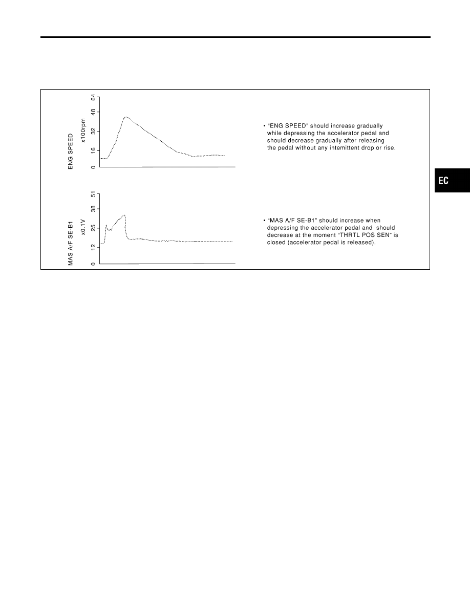
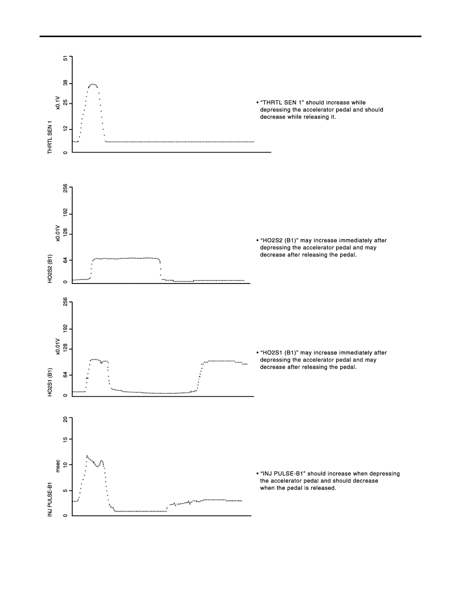
ENG SPEED, MAS A/F SE-B1, THRTL POS SEN, HO2S2 (B1), HO2S1 (B1), INJ PULSE-B1
NHEC1427S02
Below is the data for “ENG SPEED”, “MAS A/F SE-B1”, “THRTL POS SEN”, “HO2S2 (B1)”, “HO2S1 (B1)” and
“INJ PULSE-B1” when revving engine quickly up to 4,800 rpm under no load after warming up engine suffi-
ciently.
Each value is for reference, the exact value may vary.
SEF241Y
GI
MA
EM
LC
FE
AT
AX
SU
BR
ST
RS
BT
HA
SC
EL
IDX
TROUBLE DIAGNOSIS — GENERAL DESCRIPTION
Major Sensor Reference Graph in Data Monitor Mode (Cont’d)
EC-135
PBIB0668E
TROUBLE DIAGNOSIS — GENERAL DESCRIPTION
Major Sensor Reference Graph in Data Monitor Mode (Cont’d)
EC-136
Нет комментариевНе стесняйтесь поделиться с нами вашим ценным мнением.
Текст