Infiniti I35 (A33). Manual — part 329
PBIB1741E
Component Description
NHEC1347
The accelerator pedal position sensor is installed on the upper end
of the accelerator pedal assembly. The sensor detects the accel-
erator position and sends a signal to the ECM.
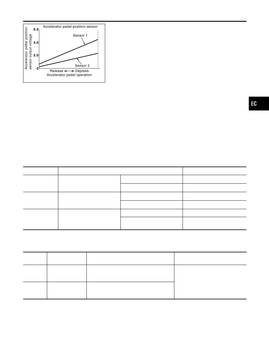
Accelerator pedal position sensor has two sensors. These sensors
are a kind of potentiometers which transform the accelerator pedal
position into output voltage, and emit the voltage signal to the ECM.
In addition, these sensors detect the opening and closing speed of
the accelerator pedal and feed the voltage signals to the ECM. The
ECM judges the current opening angle of the accelerator pedal
from these signals and controls the throttle control motor based on
these signals.
Idle position of the accelerator pedal is determined by the ECM
receiving the signal from the accelerator pedal position sensor. The
ECM uses this signal for the engine operation such as fuel cut.
CONSULT-II Reference Value in Data Monitor
Mode
NHEC1348
Specification data are reference values.
MONITOR ITEM
CONDITION
SPECIFICATION
ACCEL SEN1
I
Ignition switch: ON (engine
stopped)
I
Shift lever: D
Accelerator pedal: Released
0.41 - 0.71V
Accelerator pedal: Fully depressed
More than 3.7V
ACCEL SEN2*
I
Ignition switch: ON (engine
stopped)
I
Shift lever: D
Accelerator pedal: Released
0.15 - 0.97V
Accelerator pedal: Fully depressed
More than 3.5V
CLSD THL POS
I
Ignition switch: ON
(engine stopped)
I
Shift lever: D
Accelerator pedal: Released
ON
Accelerator pedal: Slightly
depressed
OFF
*: Accelerator pedal position sensor 2 signal is converted by ECM internally. Thus, it differs from ECM terminal voltage signal.
On Board Diagnosis Logic
NHEC1457
These self-diagnoses have the one trip detection logic.
DTC No.
Trouble diagnosis
name
DTC Detecting Condition
Possible Cause
P2127
2127
Accelerator pedal
position sensor 2 cir-
cuit low input
An excessively low voltage from the APP sensor 2
is sent to ECM.
I
Harness or connectors
(The APP sensor 2 circuit is open or
shorted.)
I
Accelerator pedal position sensor
(Accelerator pedal position sensor 2)
P2128
2128
Accelerator pedal
position sensor 2 cir-
cuit high input
An excessively high voltage from the APP sensor
2 is sent to ECM.
GI
MA
EM
LC
FE
AT
AX
SU
BR
ST
RS
BT
HA
SC
EL
IDX
DTC P2127, P2128 APP SENSOR
Component Description
EC-657
FAIL-SAFE MODE
=NHEC1457S01
When the malfunction is detected, ECM enters fail-safe mode and the MIL lights up.
Engine operating condition in fail-safe mode
The ECM controls the electric throttle control actuator in regulating the throttle opening in order for the idle position to be within
+10 degrees.
The ECM regulates the opening speed of the throttle valve to be slower than the normal condition.
So, the acceleration will be poor.
DTC Confirmation Procedure
NHEC1458
NOTE:
If DTC Confirmation Procedure has been previously conducted,
always turn ignition switch OFF and wait at least 10 seconds before
conducting the next test.
TESTING CONDITION:
Before performing the following procedure, confirm that bat-
tery voltage is more than 10V at idle.
SEF058Y
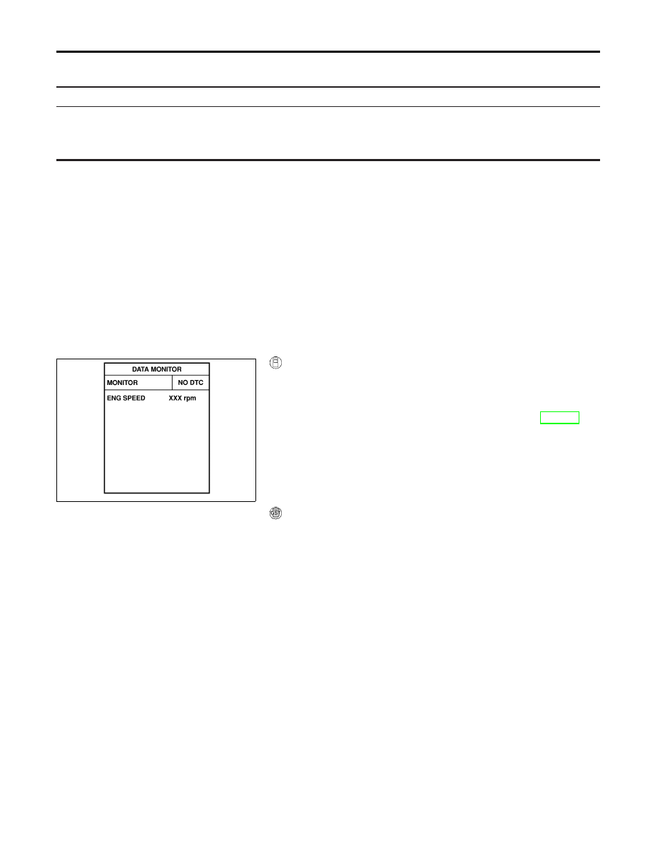
With CONSULT-II
1)
Turn ignition switch ON.
2)
Select “DATA MONITOR” mode with CONSULT-II.
3)
Start engine and let it idle for 1 second.
4)
If DTC is detected, go to “Diagnostic Procedure”, EC-660.
With GST
Follow the procedure “With CONSULT-II” above.
DTC P2127, P2128 APP SENSOR
On Board Diagnosis Logic (Cont’d)
EC-658
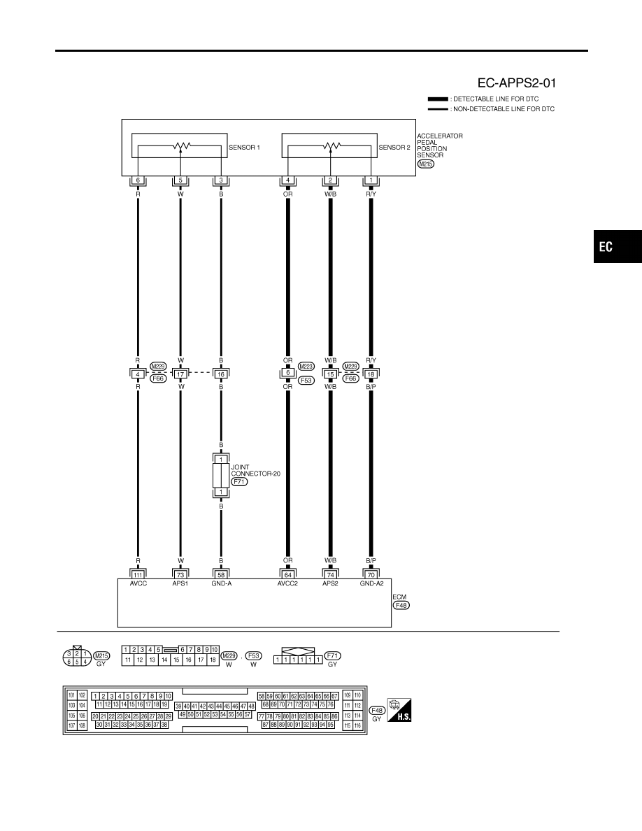
Wiring Diagram
NHEC1351
MEC646E
GI
MA
EM
LC
FE
AT
AX
SU
BR
ST
RS
BT
HA
SC
EL
IDX
DTC P2127, P2128 APP SENSOR
Wiring Diagram
EC-659
Specification data are reference values and are measured between each terminal and ground.
CAUTION:
Do not use ECM ground terminals when measuring input/output voltage. Doing so may result in dam-
age to the ECM’s transistor. Use a ground other than ECM terminals, such as the ground.
TERMI-
NAL
NO.
WIRE
COLOR
ITEM
CONDITION
DATA (DC Voltage)
58
B
Sensor ground
[Engine is running]
I
Warm-up condition
I
Idle speed
Approximately 0V
64
OR
Accelerator pedal posi-
tion sensor 2 power
supply
[Ignition switch ON]
Approximately 2.5V
70
B/P
Accelerator pedal posi-
tion sensor 2 ground
[Ignition switch ON]
Approximately 0V
73
W
Accelerator pedal posi-
tion sensor 1
[Ignition switch ON]
I
Engine stopped
I
Shift lever: D
I
Accelerator pedal released
0.41 - 0.71V
[Ignition switch ON]
I
Engine stopped
I
Shift lever: D
I
Accelerator pedal fully depressed
More than 3.7V
74
W/B
Accelerator pedal posi-
tion sensor 2
[Ignition switch ON]
I
Engine stopped
I
Shift lever: D
I
Accelerator pedal released
0.08 - 0.48V
[Ignition switch ON]
I
Engine stopped
I
Shift lever: D
I
Accelerator pedal fully depressed
More than 1.8V
111
R
Sensor power supply
[Ignition switch ON]
Approximately 5V
Diagnostic Procedure
NHEC1352
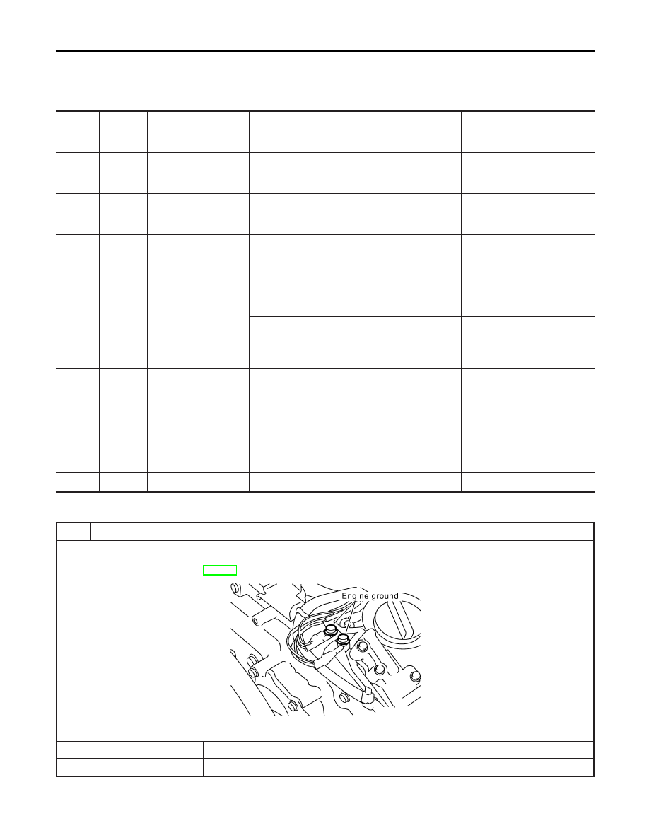
1
CHECK GROUND CONNECTIONS
1. Turn ignition switch OFF.
2. Loosen and retighten two engine ground screws.
Refer to “Ground Inspection”, EC-160.
SEC047D
OK or NG
OK
©
GO TO 2.
NG
©
Repair or replace ground connections.
DTC P2127, P2128 APP SENSOR
Wiring Diagram (Cont’d)
EC-660
Нет комментариевНе стесняйтесь поделиться с нами вашим ценным мнением.
Текст