Infiniti I35 (A33). Manual — part 330
2
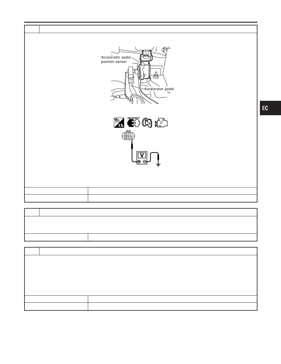
CHECK APP SENSOR 2 POWER SUPPLY CIRCUIT
1. Disconnect accelerator pedal position (APP) sensor harness connector.
2. Turn ignition switch ON.
SEC081D
3. Check voltage between APP sensor terminal 4 and ground with CONSULT-II or tester.
SEC094D
Voltage: Approximately 2.5V
OK or NG
OK
©
GO TO 4.
NG
©
GO TO 3.
3
DETECT MALFUNCTIONING PART
Check the following.
I
Harness connectors M223, F53
I
Harness for open or short between ECM and accelerator pedal position sensor
©
Repair open circuit or short to ground or short to power in harness or connectors.
4
CHECK APP SENSOR 2 GROUND CIRCUIT FOR OPEN AND SHORT
1. Turn ignition switch OFF.
2. Disconnect ECM harness connector.
3. Check harness continuity between APP sensor terminal 1 and ECM terminal 70.
Refer to Wiring Diagram.
Continuity should exist.
4. Also check harness for short to ground and short to power.
OK or NG
OK
©
GO TO 6.
NG
©
GO TO 5.
GI
MA
EM
LC
FE
AT
AX
SU
BR
ST
RS
BT
HA
SC
EL
IDX
DTC P2127, P2128 APP SENSOR
Diagnostic Procedure (Cont’d)
EC-661
5
DETECT MALFUNCTIONING PART
Check the following.
I
Harness connectors M229, F66
I
Harness for open or short between ECM and accelerator pedal position sensor
©
Repair open circuit or short to ground or short to power in harness or connectors.
6
CHECK APP SENSOR 2 INPUT SIGNAL CIRCUIT FOR OPEN AND SHORT
1. Check harness continuity between ECM terminal 74 and APP sensor terminal 2.
Refer to Wiring Diagram.
Continuity should exist.
2. Also check harness for short to ground and short to power.
OK or NG
OK
©
GO TO 8.
NG
©
GO TO 7.
7
DETECT MALFUNCTIONING PART
Check the following.
I
Harness connectors M229, F66
I
Harness for open or short between ECM and accelerator pedal position sensor
©
Repair open circuit or short to ground or short to power in harness or connectors.
8
CHECK APP SENSOR
Refer to “Component Inspection”, EC-662.
OK or NG
OK
©
GO TO 9.
NG
©
Replace accelerator pedal assembly.
9
CHECK INTERMITTENT INCIDENT
Refer to “TROUBLE DIAGNOSIS FOR INTERMITTENT INCIDENT”, EC-152.
©
INSPECTION END
SEC901C
Component Inspection
NHEC1459
ACCELERATOR PEDAL POSITION SENSOR
1.
Reconnect all harness connectors disconnected.
2.
Turn ignition switch ON.
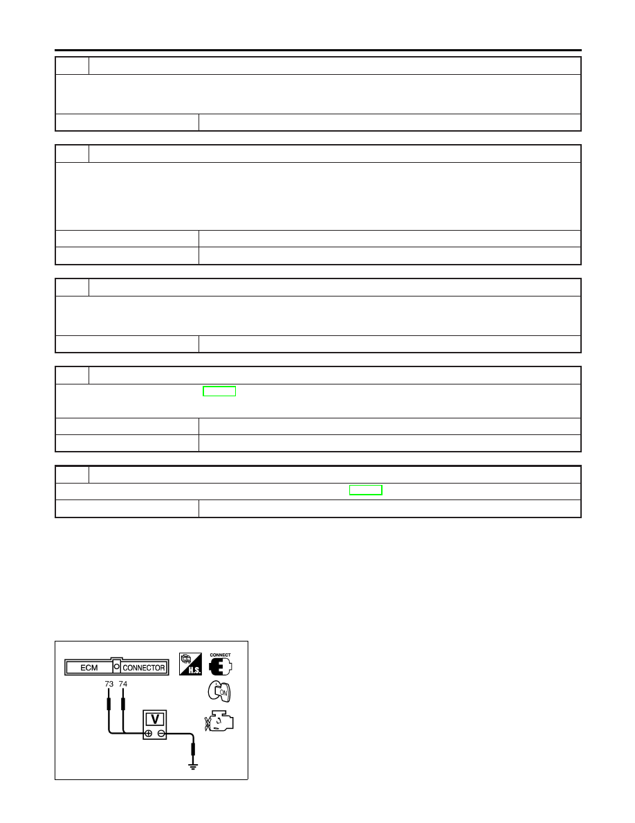
3.
Check voltage between ECM terminals 73 (APP sensor 1
signal), 74 (APP sensor 2 signal) and ground under the follow-
ing conditions.
DTC P2127, P2128 APP SENSOR
Diagnostic Procedure (Cont’d)
EC-662

Terminal
Accelerator pedal
Voltage
73
(Accelerator pedal posi-
tion sensor 1)
Released
0.41 - 0.71V
Fully depressed
More than 3.7V
74
(Accelerator pedal posi-
tion sensor 2)
Released
0.08 - 0.48V
Fully depressed
More than 1.8V
4.
If NG, replace accelerator pedal assembly.
5.
Perform “Accelerator Pedal Released Position Learning”,
EC-70.
6.
Perform “Throttle Valve Closed Position Learning”, EC-70.
7.
Perform “Idle Air Volume Learning”, EC-70.
GI
MA
EM
LC
FE
AT
AX
SU
BR
ST
RS
BT
HA
SC
EL
IDX
DTC P2127, P2128 APP SENSOR
Component Inspection (Cont’d)
EC-663

PBIB0145E
Component Description
NHEC1365
Electric throttle control actuator consists of throttle control motor,
throttle position sensor, etc. The throttle position sensor responds
to the throttle vale movement.
The throttle position sensor has the two sensors. These sensors
are a kind of potentiometers which transform the throttle valve
position into output voltage, and emit the voltage signal to the ECM.
In addition, these sensors detect the opening and closing speed of
the throttle valve and feed the voltage signals to the ECM. The
ECM judges the current opening angle of the throttle valve form
these signal and the ECM controls the throttle control motor to
make the throttle valve opening angle properly in response to driv-
ing condition.
CONSULT-II Reference Value in Data Monitor
Mode
NHEC1366
Specification data are reference values.
MONITOR ITEM
CONDITION
SPECIFICATION
THRTL SEN1
THRTL SEN2*
I
Ignition switch:
ON (Engine stopped)
I
Shift lever: D
Accelerator pedal: Released
More than 0.36V
Accelerator pedal: Fully depressed
Less than 4.75V
*: Throttle position sensor 2 signal is converted by ECM internally. Thus, it differs from ECM terminal voltage signal.
On Board Diagnosis Logic
NHEC1434
This self-diagnosis has the one trip detection logic.
NOTE:
If DTC P2135 is displayed with DTC P1229, first perform the trouble diagnosis for DTC P1229. Refer to
EC-539.
DTC No.
Trouble diagnosis
name
DTC Detecting Condition
Possible Cause
P2135
2135
Throttle position sen-
sor circuit range/
performance problem
Rationally incorrect voltage is sent to ECM com-
pared with the signals from TP sensor 1 and TP
sensor 2.
I
Harness or connector
(The TP sensor 1 and 2 circuit is
open or shorted.)
I
Electric throttle control actuator (TP
sensor 1 and 2)
FAIL-SAFE MODE
NHEC1434S01
When the malfunction is detected, the ECM enters fail-safe mode and the MIL lights up.
Engine operation condition in fail-safe mode
The ECM controls the electric throttle control actuator in regulating the throttle opening in order for the idle position to be within
+10 degrees.
The ECM regulates the opening speed of the throttle valve to be slower than the normal condition.
So, the acceleration will be poor.
DTC P2135 TP SENSOR
Component Description
EC-664
Нет комментариевНе стесняйтесь поделиться с нами вашим ценным мнением.
Текст