Infiniti I35 (A33). Manual — part 106
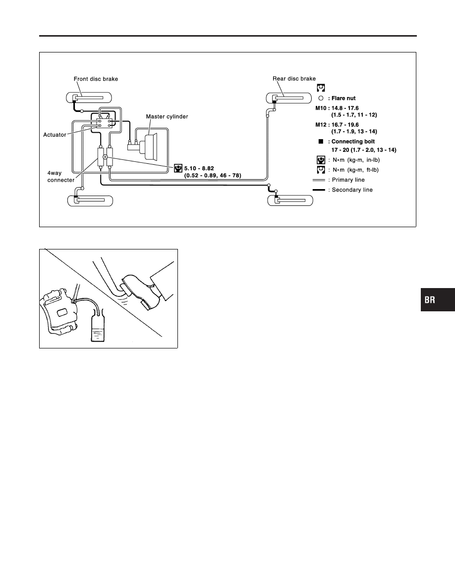
Hydraulic Circuit
NHBR0010
SBR885EA
SBR992
Removal
NHBR0011
CAUTION:
I
Be careful not to splash brake fluid on painted areas; it
may cause paint damage. If brake fluid is splashed on
painted areas, wash it away with water immediately.
I
All hoses must be free from excessive bending, twisting
and pulling.
1.
Connect vinyl tube to bleed valve.
2.
Drain brake fluid from each bleed valve by depressing brake
pedal.
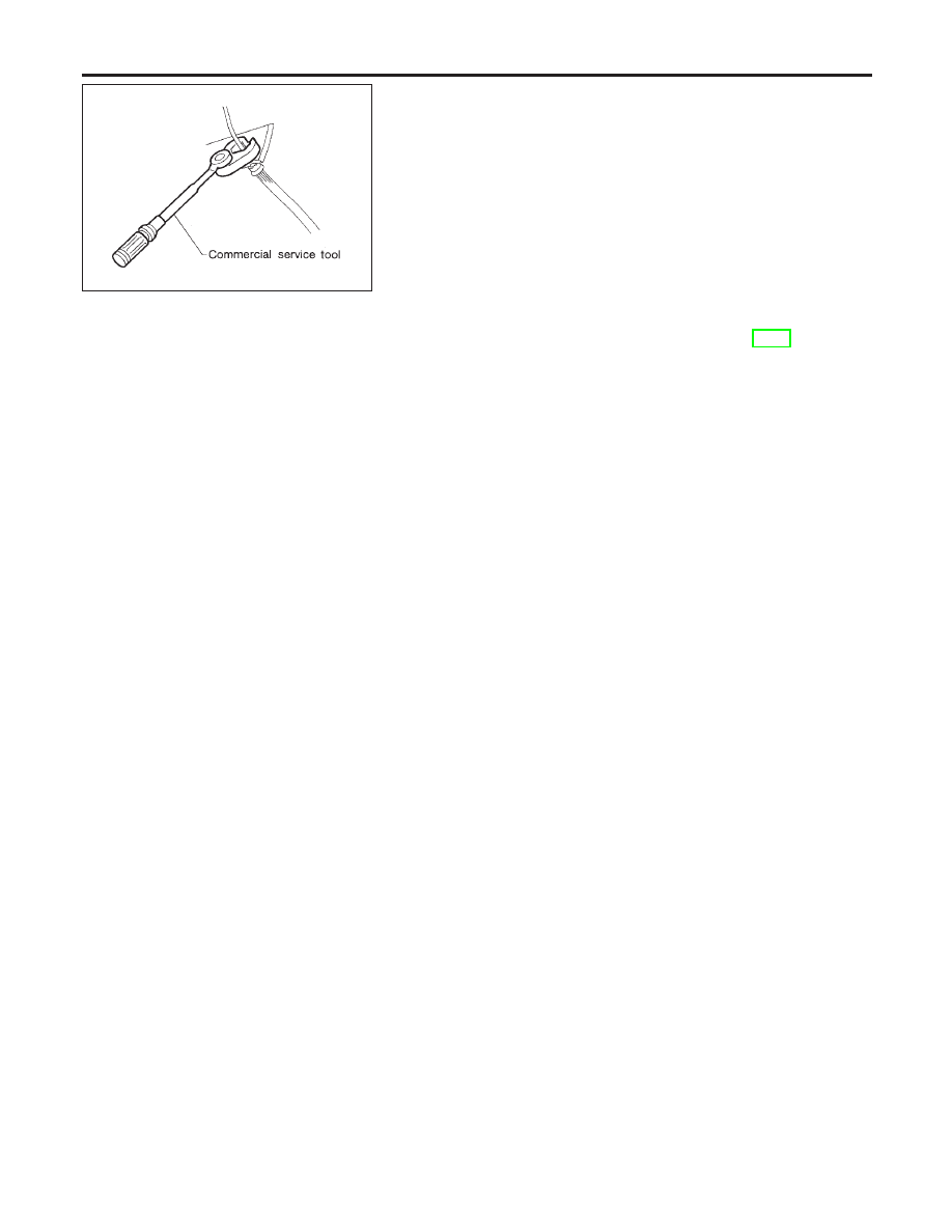
3.
Remove flare nut connecting brake tube and hose, then with-
draw lock spring.
4.
Cover openings to prevent entrance of dirt whenever discon-
necting brake line.
Inspection
NHBR0012
Check brake lines (tubes and hoses) for cracks, deterioration or
other damage. Replace any damaged parts.
GI
MA
EM
LC
EC
FE
AT
AX
SU
ST
RS
BT
HA
SC
EL
IDX
BRAKE HYDRAULIC LINE
Hydraulic Circuit
BR-9
SBR686C
Installation
NHBR0013
CAUTION:
I
Refill with new brake fluid “DOT 3”.
I
Never reuse drained brake fluid.
1.
Tighten all flare nuts and connecting bolts.
Specification:
Flare nut
M10: 14.8 - 17.6 N·m (1.5 - 1.7 kg-m, 11 - 12 ft-lb)
M12: 16.7 - 19.6 N·m (1.7 - 1.9 kg-m, 13 - 14 ft-lb)
Connecting bolt
17 - 20 N·m (1.8 - 2.0 kg-m, 13 - 14 ft-lb)
2.
Refill until new brake fluid comes out of each bleed valve.
3.
Bleed air. Refer to “Bleeding Brake System”, BR-8.
BRAKE HYDRAULIC LINE
Installation
BR-10
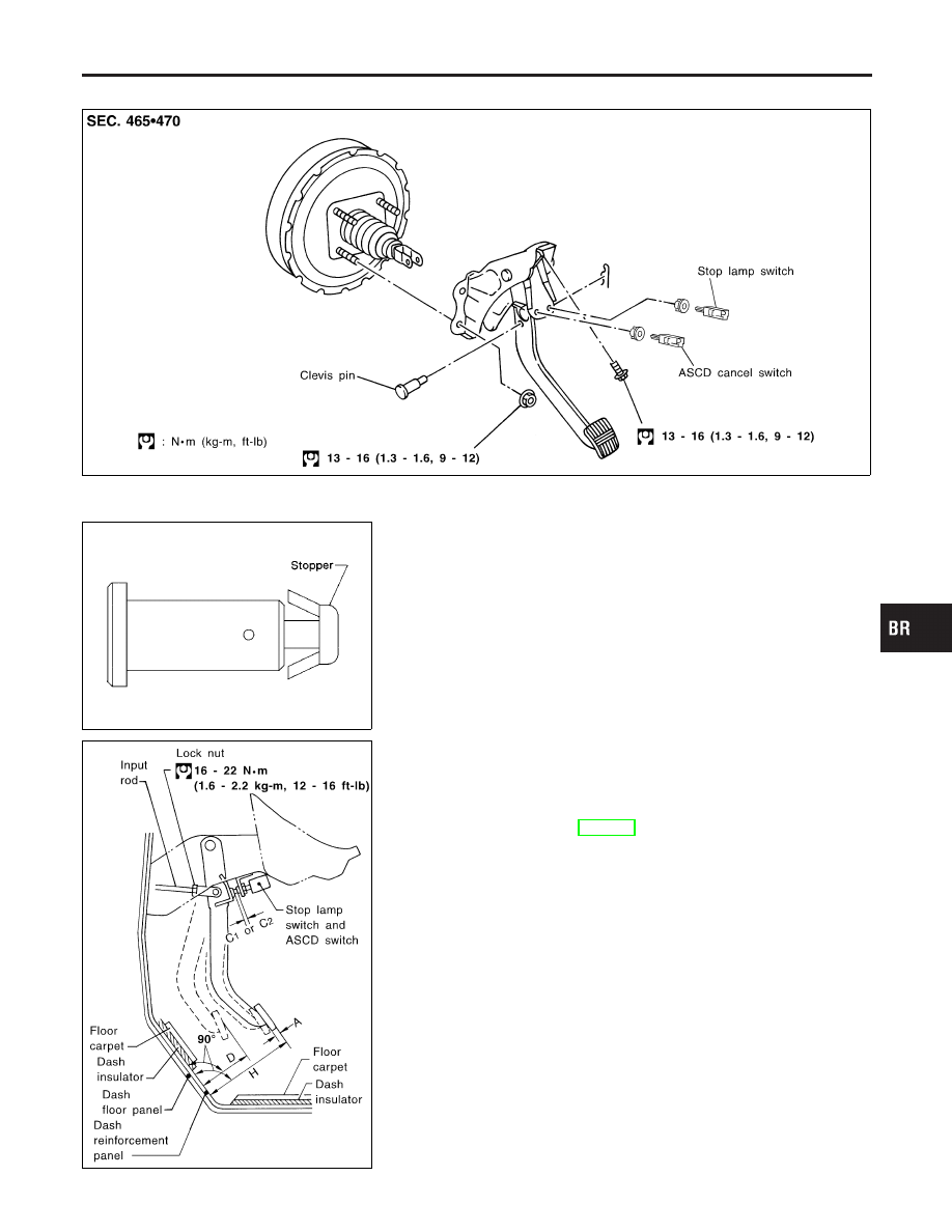
Removal and Installation
NHBR0015
SBR525EB
SBR997
Inspection
NHBR0016
Check brake pedal for following items.
I
Brake pedal bend
I
Clevis pin deformation
I
Crack of any welded portion
I
Crack or deformation of clevis pin stopper
SBR526E
Adjustment
NHBR0017
Check brake pedal free height from metal panel. Adjust if neces-
sary.
H: Free height
Refer to SDS, BR-172.
C
1
, C
2
: Clearance between pedal stopper and threaded
end of stop lamp switch and ASCD switch
0.74 - 1.96 mm (0.0291 - 0.0772 in)
D: Depressed height
82.5 mm (3.248 in)
Under force of 490 N (50 kg, 110 lb) with engine run-
ning.
GI
MA
EM
LC
EC
FE
AT
AX
SU
ST
RS
BT
HA
SC
EL
IDX
BRAKE PEDAL AND BRACKET
Removal and Installation
BR-11
SBR229E
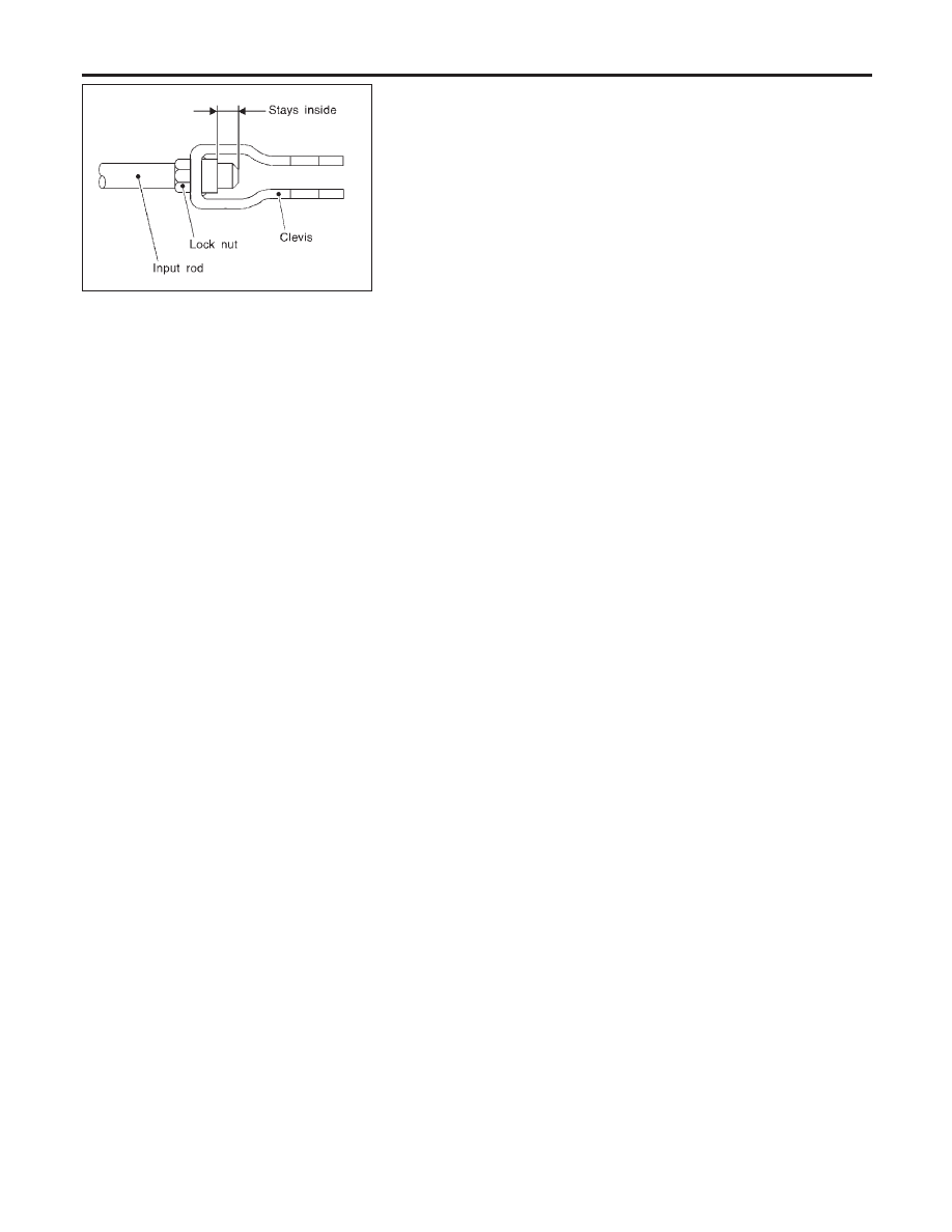
1.
Loosen lock nut and adjust pedal free height by turning brake
booster input rod. Then tighten lock nut.
2.
Check pedal free play.
Make sure that stop lamps go off when pedal is released.
3.
Check brake pedal’s depressed height while engine is running.
If lower than specification, check brake system for leaks, accu-
mulation of air or any damage to components (master cylinder,
wheel cylinder, etc.); then make necessary repairs.
BRAKE PEDAL AND BRACKET
Adjustment (Cont’d)
BR-12
Нет комментариевНе стесняйтесь поделиться с нами вашим ценным мнением.
Текст