Infiniti I35 (A33). Manual — part 104
BRAKE SYSTEM
CONTENTS
PRECAUTIONS . . . . . . . . . . . . . . . ...4
Precautions for Supplemental Restraint System
(SRS)
. . . . . . . . . . . . . ..4
Precautions for Brake System. . . . . . . . . .4
Wiring Diagrams and Trouble Diagnosis. . . . . .4
PREPARATION . . . . . . . . . . . . . . . ...5
Commercial Service Tools . . . . . . . . . . ...5
NOISE, VIBRATION AND HARSHNESS (NVH)
TROUBLESHOOTING . . . . . . . . . . . . . .6
NVH Troubleshooting Chart. . . . . . . . . . .6
ON-VEHICLE SERVICE . . . . . . . . . . . . ..7
Checking Brake Fluid Level. . . . . . . . . . .7
Checking Brake Line . . . . . . . . . . . . ...7
Changing Brake Fluid . . . . . . . . . . . . ..7
Brake Burnishing Procedure. . . . . . . . . . 7
Bleeding Brake System . . . . . . . . . . . ...8
BRAKE HYDRAULIC LINE . . . . . . . . . . . .9
Hydraulic Circuit. . . . . . . . . . . . . . ...9
Removal. . . . . . . . . . . . . . . . . ...9
Inspection. . . . . . . . . . . . . . . . . .9
Installation. . . . . . . . . . . . . . . . ..10
BRAKE PEDAL AND BRACKET. . . . . . . . .. 11
Removal and Installation . . . . . . . . . . ... 11
Inspection. . . . . . . . . . . . . . . . ... 11
Adjustment . . . . . . . . . . . . . . . . . 11
MASTER CYLINDER (TOKICO) . . . . . . . . ...13
Removal. . . . . . . . . . . . . . . . . .13
Disassembly. . . . . . . . . . . . . . . ...14
Inspection. . . . . . . . . . . . . . . . ...14
Assembly . . . . . . . . . . . . . . . . ...14
Installation. . . . . . . . . . . . . . . . ..15
MASTER CYLINDER [BOSCH (NABCO)] . . . . ...16
Removal. . . . . . . . . . . . . . . . . .16
Disassembly. . . . . . . . . . . . . . . ...17
Inspection. . . . . . . . . . . . . . . . ...17
Assembly . . . . . . . . . . . . . . . . ...17
Installation. . . . . . . . . . . . . . . . ..18
BRAKE BOOSTER. . . . . . . . . . . . . . 19
On-vehicle Service. . . . . . . . . . . . . .19
. . . . . . . . . . . ...19
. . . . . . . . . . . . ...19
Removal. . . . . . . . . . . . . . . . . .19
Inspection. . . . . . . . . . . . . . . . ...19
. . . . . . . ..19
Installation. . . . . . . . . . . . . . . . ..19
VACUUM HOSE. . . . . . . . . . . . . . . .21
Removal and Installation . . . . . . . . . . ...21
Inspection. . . . . . . . . . . . . . . . ...21
. . . . . . . . ...21
. . . . . . . . . . . . . . 21
FRONT DISC BRAKE . . . . . . . . . . . . ...22
Component . . . . . . . . . . . . . . . . 22
Pad Replacement . . . . . . . . . . . . . ..22
Removal. . . . . . . . . . . . . . . . . .23
Disassembly. . . . . . . . . . . . . . . ...23
Inspection. . . . . . . . . . . . . . . . ...24
. . . . . . . . . . . . . . . . .24
. . . . . . . . . . . . . . . . ...24
Assembly . . . . . . . . . . . . . . . . ...25
Installation. . . . . . . . . . . . . . . . ..25
REAR DISC BRAKE. . . . . . . . . . . . . ..26
Component . . . . . . . . . . . . . . . . 26
Pad Replacement . . . . . . . . . . . . . ..26
Removal. . . . . . . . . . . . . . . . . .28
Disassembly. . . . . . . . . . . . . . . ...29
Inspection. . . . . . . . . . . . . . . . ...30
. . . . . . . . . . . . . . . . .30
. . . . . . . . . . . . . . . . ...30
Assembly . . . . . . . . . . . . . . . . ...31
Installation. . . . . . . . . . . . . . . . ..33
PARKING BRAKE CONTROL . . . . . . . . . ..34
Components. . . . . . . . . . . . . . . ...34
Removal and Installation . . . . . . . . . . ...34
Inspection. . . . . . . . . . . . . . . . ...34
Adjustment . . . . . . . . . . . . . . . . .35
GI
MA
EM
LC
EC
FE
AT
AX
SU
ST
RS
BT
HA
SC
EL
IDX

TCS
DESCRIPTION . . . . . . . . . . . . . . . ...36
Purpose. . . . . . . . . . . . . . . . . ..36
ABS (Anti-Lock Brake System) Operation . . . . 36
ABS Hydraulic Circuit . . . . . . . . . . . . 36
TCS (Traction Control System) Operation . . . . 37
System Components . . . . . . . . . . . . .37
System Description. . . . . . . . . . . . . 38
. . . . . . . . . . . . . . . . .38
. . . . . . . . . . . . . ..38
. . . . . . . . . . . . . . . .38
Component Parts and Harness Connector
Location . . . . . . . . . . . . . . . . . .40
Schematic . . . . . . . . . . . . . . . . ..41
Wiring Diagram - TCS -. . . . . . . . . . . .42
ON BOARD DIAGNOSTIC SYSTEM
DESCRIPTION . . . . . . . . . . . . . . . ...46
CONSULT-II Functions . . . . . . . . . . . ..46
. . . . . . . . ..46
CONSULT-II Inspection Procedure. . . . . . . 46
. . . . . ...48
. . . . . . . . 49
. . . . . . . . . 49
. . . . . . . . . . ...50
. . . . . . . . . . . ...52
TROUBLE DIAGNOSIS - INTRODUCTION. . . . ..53
How to Perform Trouble Diagnoses for Quick
and Accurate Repair . . . . . . . . . . . . ..53
. . . . . . . . . . . . . ..53
TROUBLE DIAGNOSIS - BASIC INSPECTION . . ...54
Preliminary Check. . . . . . . . . . . . . ..54
Ground Circuit Check . . . . . . . . . . . . 57
ABS ACTUATOR AND ELECTRIC UNIT
(CONTROL UNIT) GROUND
TROUBLE DIAGNOSIS - GENERAL
DESCRIPTION . . . . . . . . . . . . . . . ...58
Malfunction Code/Symptom Chart. . . . . . . .58
CAN COMMUNICATION . . . . . . . . . . . ...60
System Description. . . . . . . . . . . . . 60
TROUBLE DIAGNOSES FOR SELF-DIAGNOSTIC
ITEMS. . . . . . . . . . . . . . . . . . . .61
Wheel Sensor or Rotor. . . . . . . . . . . ..61
. . . . . . . . . .61
ABS Actuator Solenoid Valve or Solenoid Valve
Relay. . . . . . . . . . . . . . . . . . ..65
. . . . . . . . . .65
Motor Relay or Motor. . . . . . . . . . . . .68
. . . . . . . . . .68
Low Voltage . . . . . . . . . . . . . . . ...70
. . . . . . . . . .70
Control Unit. . . . . . . . . . . . . . . . 72
. . . . . . . . . .72
CAN Communication Line . . . . . . . . . . .73
. . . . . . . . . .73
Engine System. . . . . . . . . . . . . . ...73
. . . . . . . . . .73
A/T System . . . . . . . . . . . . . . . . 74
. . . . . . . . . .74
TROUBLE DIAGNOSES FOR SYMPTOMS . . . . .75
1. ABS Works Frequently . . . . . . . . . . ..75
2. Unexpected Pedal Action . . . . . . . . . ..75
3. Long Stopping Distance . . . . . . . . . . 76
4. ABS Does Not Work. . . . . . . . . . . ..77
5. Pedal Vibration and Noise. . . . . . . . . .78
6. ABS Warning Lamp Does Not Come On
When Ignition Switch Is Turned On. . . . . . ...79
7. ABS Warning Lamp Stays On When Ignition
Switch Is Turned On . . . . . . . . . . . . ..80
8. SLIP Indicator Lamp Does Not Come On
When Ignition Switch Is Turned On. . . . . . ...83
9. TCS OFF Indicator Lamp Does Not Come On
When Ignition Switch Is Turned On. . . . . . ...84
10. TCS OFF Switch Is Inoperative . . . . . . ..86
11. Poor Acceleration. . . . . . . . . . . . .89
ABS ACTUATOR AND ELECTRIC UNIT
(CONTROL UNIT). . . . . . . . . . . . . . ..90
Removal. . . . . . . . . . . . . . . . . .90
Installation. . . . . . . . . . . . . . . . ..90
VDC
PRECAUTIONS . . . . . . . . . . . . . . . .91
Precautions for Supplemental Restraint System
(SRS)
. . . . . . . . . . . . . 91
Precautions for Brake System. . . . . . . . ...91
Precautions for Brake Control . . . . . . . . ...92
ON-VEHICLE SERVICE . . . . . . . . . . . . 93
Adjustment of Neutral Position of Steering Angle
Sensor. . . . . . . . . . . . . . . . . . 93
GENERAL INFORMATION . . . . . . . . . . ...95
Fail-safe . . . . . . . . . . . . . . . . . .95
. . . . . . . . . . . . . . ..95
. . . . . . . . . . . . ..95
Hydraulic Circuit. . . . . . . . . . . . . . .96
ABS Functions . . . . . . . . . . . . . . ...96
TCS Functions . . . . . . . . . . . . . . ...97
VDC Functions. . . . . . . . . . . . . . ...97
System Diagram . . . . . . . . . . . . . . 98
CAN COMMUNICATION . . . . . . . . . . . ...99
System Description. . . . . . . . . . . . . 99
TROUBLE DIAGNOSIS - INTRODUCTION. . . . 100
How to Perform Trouble Diagnoses for Quick
and Accurate Repair . . . . . . . . . . . . 100
. . . . . . . . . . . . . 100
CONTENTS
(Cont’d)
BR-2
. . . . . . . . . . . . . . 101
. . . . . . . . . . ..102
. . . . . . .102
Component Parts and Harness Connector
Location . . . . . . . . . . . . . . . . ...103
Schmatic . . . . . . . . . . . . . . . . ..104
Wiring Diagram -VDC/TCS/ABS- . . . . . . . 105
Control Unit Input/Output Signal Standard. . . .. 113
STANDARDS USING A CIRCUIT TESTER AND
OSCILLOSCOPE
. . . . . . . . . . . . ... 113
. . . . . . . 116
CONSULT-II Functions . . . . . . . . . . . 118
. . . . . . . . 118
. . . . . . . . . . . . . 119
. . . . . . . . . . . . . 123
. . . . . . . . . . . . . . 126
For Correct and Quick Diagnosis . . . . . . . 129
PRECAUTIONS FOR TROUBLE DIAGNOSIS
. . ..129
TROUBLE DIAGNOSIS - BASIC INSPECTION . . .131
Preliminary Check 1: (Brake Fluid Level and
Leak Inspection) . . . . . . . . . . . . . ..131
Preliminary Check 2: (Inspection for Loose
Power Supply Terminal). . . . . . . . . . ...131
Preliminary Check 3: (Inspection for ABS
Warning Lamp, VDC OFF Indicator Lamp, and
SLIP Indicator Lamp). . . . . . . . . . . ...131
TROUBLE DIAGNOSES FOR SELF-DIAGNOSTIC
ITEMS. . . . . . . . . . . . . . . . . . ...133
Inspection 1 Wheel Sensor and Circuit. . . . ...133
Inspection 2 Engine System. . . . . . . . . 135
Inspection 3 VDC/TCS/ABS Control Unit System...136
Inspection 4 Pressure Sensor and The Circuit
Between Pressure Sensor and VDC/TCS/ABS
Control Unit. . . . . . . . . . . . . . . ..137
Inspection 5 Steering Angle Sensor and The
Circuit Between Steering Angle Sensor and
VDC/TCS/ABS . . . . . . . . . . . . . . .139
Inspection 6 Yaw Rate/Side G and The Circuit
Between Yaw Rate/Side G and VDC/TCS/ABS
Control Unit. . . . . . . . . . . . . . . ..141
Inspection 7 Solenoid Valve, VDC Switch-over
Solenoid Valve and Circuit . . . . . . . . . ..142
Inspection 8 Actuator Motor, Motor Relay and
Circuit. . . . . . . . . . . . . . . . . ...146
Inspection 9 Actuator Relay and Circuit . . . . ..148
Inspection 10 Stop Lamp Switch and Circuit . . ..150
Inspection 11 VDC/TCS/ABS Control Unit Power
Supply Circuit. . . . . . . . . . . . . . ...151
Inspection 12 When
Indicated in The Self-diagnosis Results . . . . ..154
Inspection 13 When
Indicated in The Self-diagnosis Results . . . . ..154
Inspection 14 Brake Fluid Level of Reservoir
Tank . . . . . . . . . . . . . . . . . . .155
Inspection 15 CAN Communication Circuit, VDC/
TCS/ABS Control Unit and Steering Angle
Sensor. . . . . . . . . . . . . . . . . ..156
Component Check . . . . . . . . . . . . ...157
. . . . . . . . . . . . 157
. . . . . . . . . . . . ..157
. . . . . . . . . . . . ...158
TROUBLE DIAGNOSES FOR SYMPTOMS . . . ...160
Symptom 1: ABS Works Frequently. . . . . . 160
Symptom 2: Unexpected Pedal Action. . . . . 160
Symptom 3: Longer Stopping Distance. . . . ...161
Symptom 4: ABS Does Not Work . . . . . . ...162
Symptom 5: Pedal Vibration and Noise . . . . ..162
Symptom 6: VDC OFF Indicator Lamp Does Not
Illuminate. . . . . . . . . . . . . . . . ..163
Symptom 7: SLIP Indicator Lamp Does Not
Illuminate. . . . . . . . . . . . . . . . ..164
Symptom 8: During VDC/TCS/ABS Control,
Vehicle Behavior is Jerky . . . . . . . . . . 164
VDC/TCS/ABS CONTROL UNIT. . . . . . . . .166
Removal and Installation . . . . . . . . . . .166
. . . . . . . . . . . . . . . .166
. . . . . . . . . . . . . ..166
ABS ACTUATOR AND VDC RELAY BOX . . . . 167
Removal and Installation . . . . . . . . . . .167
YAW RATE/SIDE G SENSOR. . . . . . . . . .168
Removal and Installation . . . . . . . . . . .168
. . . . . . . . . . . . . . . .168
. . . . . . . . . . . . . ..168
VDC OFF SWITCH . . . . . . . . . . . . . ..169
Removal and Installation . . . . . . . . . . .169
. . . . . . . . . . . . . . . .169
. . . . . . . . . . . . . ..169
TCS/VDC
REMOVAL AND INSTALLATION . . . . . . . ...170
Wheel Sensors . . . . . . . . . . . . . . 170
Sensor Rotor. . . . . . . . . . . . . . . 170
. . . . . . . . . . . . . . . .170
. . . . . . . . . . . . . ..171
SERVICE DATA AND SPECIFICATIONS (SDS) . ...172
General Specifications. . . . . . . . . . . .172
Disc Brake . . . . . . . . . . . . . . . ...172
Brake Pedal . . . . . . . . . . . . . . . .172
Parking Brake . . . . . . . . . . . . . . ..172
Brake Booster . . . . . . . . . . . . . . ..172
ABS Wheel Sensor. . . . . . . . . . . . ..172
GI
MA
EM
LC
EC
FE
AT
AX
SU
ST
RS
BT
HA
SC
EL
IDX
CONTENTS
(Cont’d)
BR-3
Precautions for Supplemental Restraint System
(SRS) “AIR BAG” and “SEAT BELT
PRE-TENSIONER”
NHBR0127
The Supplemental Restraint System such as “AIR BAG” and “SEAT BELT PRE-TENSIONER”, used along with
a front seat belt, helps to reduce the risk or severity of injury to the driver and front passenger for certain types
of collision. This system includes seat belt switch inputs and dual stage front air bag modules. The SRS sys-
tem uses the seat belt switches to determine the front air bag deployment, and may only deploy one front air
bag, depending on the severity of a collision and whether the front occupants are belted or unbelted.
Information that is necessary to service the system safely is included in the RS section of this Service Manual.
WARNING:
I
To avoid rendering the SRS inoperative, which could increase the risk of personal injury or death
in the event of a collision which would result in air bag inflation, all maintenance must be performed
by an authorized NISSAN/INFINITI dealer.
I
Improper maintenance, including incorrect removal and installation of the SRS, can lead to per-
sonal injury caused by unintentional activation of the system. For removal of Spiral Cable and Air
Bag Module, see the RS section.
I
Do not use electrical test equipment on any circuit related to the SRS unless instructed to in this
Service Manual. SRS wiring harnesses can be identified by yellow and/or orange harnesses or
harness connectors.
SBR686C
Precautions for Brake System
NHBR0002
I
Recommended fluid is brake fluid “DOT 3”.
I
Never reuse drained brake fluid.
I
Be careful not to splash brake fluid on painted areas.
I
To clean or wash all parts of master cylinder, disc brake
caliper and wheel cylinder, use clean brake fluid.
I
Never use mineral oils such as gasoline or kerosene. They
will ruin rubber parts of the hydraulic system.
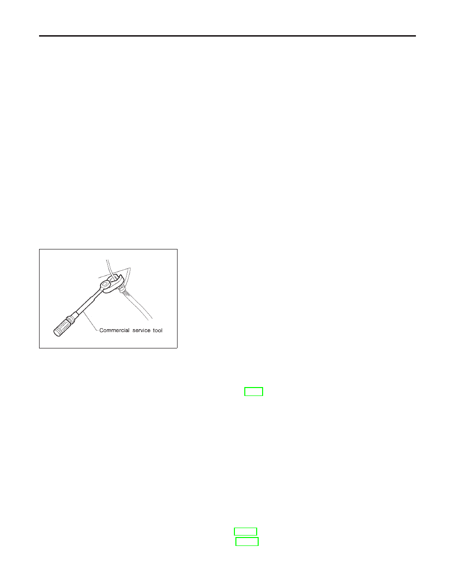
I
Use flare nut wrench when removing and installing brake
tube.
I
When installing brake piping, be sure to check torque.
I
Burnish the brake contact surfaces after refinishing or
replacing drums or rotors, after replacing pads or linings,
or if a soft pedal occurs at very low mileage.
Refer to “Brake Burnishing Procedure”, “ON-VEHICLE
SERVICE”, BR-7.
WARNING:
I
Clean brake pads and shoes with a waste cloth, then wipe
with a dust collector.
Wiring Diagrams and Trouble Diagnosis
NHBR0003
When you read wiring diagrams, refer to the following:
I
“HOW TO READ WIRING DIAGRAMS” in GI section
I
“POWER SUPPLY ROUTING” for power distribution circuit in EL section
When you perform trouble diagnosis, refer to the following:
I
“HOW TO FOLLOW TEST GROUP IN TROUBLE DIAGNOSIS” in GI section
I
“HOW TO PERFORM EFFICIENT DIAGNOSIS FOR AN ELECTRICAL INCIDENT” in GI section
I
For trouble diagnoses of models with TCS. Refer to BR-36.
I
For trouble diagnoses of models with VDC. Refer to BR-95.
PRECAUTIONS
Precautions for Supplemental Restraint System (SRS) “AIR BAG” and “SEAT BELT PRE-TENSIONER”
BR-4
Нет комментариевНе стесняйтесь поделиться с нами вашим ценным мнением.
Текст