Infiniti I35 (A33). Manual — part 233
On Board Diagnosis Logic
NHEC0912
With the Air/Fuel Mixture Ratio Self-Learning Control, the actual
mixture ratio can be brought closely to the theoretical mixture ratio
based on the mixture ratio feedback signal from the heated oxygen
sensors 1. The ECM calculates the necessary compensation to
correct the offset between the actual and the theoretical ratios.
In case the amount of the compensation value is extremely large
(The actual mixture ratio is too lean.), the ECM judges the condi-
tion as the fuel injection system malfunction and lights up the MIL
(2 trip detection logic).
Sensor
Input Signal to ECM
ECM func-
tion
Actuator
Heated oxygen sensor 1
Density of oxygen in exhaust gas
(Mixture ratio feedback signal)
Fuel injec-
tion control
Injector
DTC No.
Trouble diagnosis
name
DTC Detecting Condition
Possible Cause
P0171
0171
(Bank 1)
P0174
0174
(Bank 2)
Fuel injection system
too lean
Fuel injection system does not operate properly,
the amount of mixture ratio compensation is too
large. (The mixture ratio is too lean.)
I
Intake air leaks
I
Heated oxygen sensor 1
I
Injector
I
Exhaust gas leaks
I
Incorrect fuel pressure
I
Lack of fuel
I
Mass air flow sensor
I
Incorrect PCV hose connection
SEF968Y
DTC Confirmation Procedure
NHEC0913
NOTE:
If DTC Confirmation Procedure has been previously conducted,
always turn ignition switch OFF and wait at least 10 seconds before
conducting the next test.
WITH CONSULT-II
NHEC0913S01
1)
Start engine and warm it up to normal operating temperature.
2)
Turn ignition switch OFF and wait at least 10 seconds.
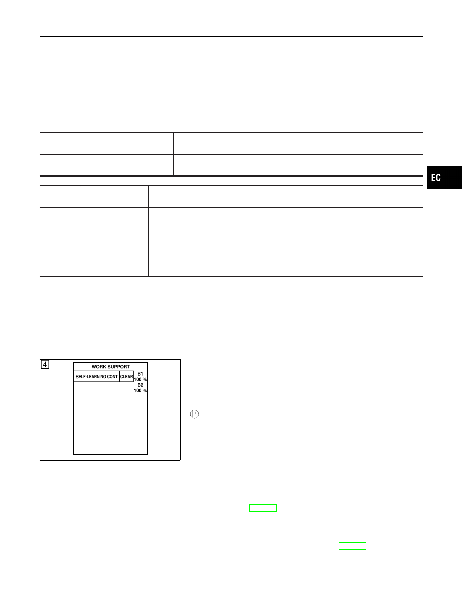
3)
Turn ignition switch ON and select “SELF-LEARN CONTROL”
in “WORK SUPPORT” mode with CONSULT-II.
4)
Clear the self-learning control coefficient by touching “CLEAR”.
5)
Select “DATA MONITOR” mode with CONSULT-II.
6)
Start engine again and let it idle for at least 10 minutes.
The 1st trip DTC P0171 or P0174 should be detected at this
stage, if a malfunction exists. If so, go to “Diagnostic
Procedure”, EC-277.
7)
If it is difficult to start engine at step 6, the fuel injection sys-
tem has a malfunction, too.
8)
Crank engine while depressing accelerator pedal. If engine
starts, go to “Diagnostic Procedure”, EC-277. If engine does
not start, check exhaust and intake air leak visually.
GI
MA
EM
LC
FE
AT
AX
SU
BR
ST
RS
BT
HA
SC
EL
IDX
DTC P0171, P0174 FUEL INJECTION SYSTEM FUNCTION
On Board Diagnosis Logic
EC-273
SEC055D
WITH GST
NHEC0913S02
1)
Start engine and warm it up to normal operating temperature.
2)
Turn ignition switch OFF and wait at least 10 seconds.
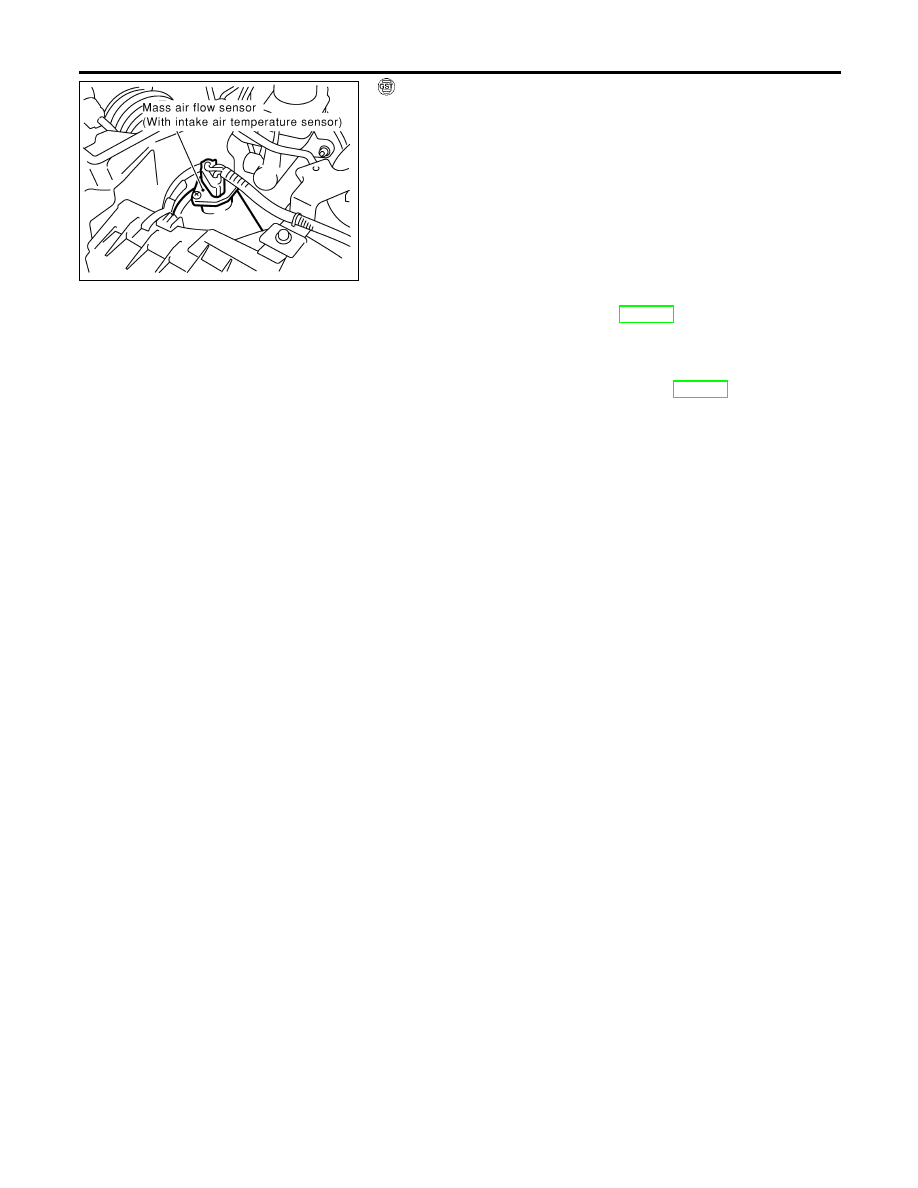
3)
Disconnect mass air flow sensor harness connector. Then
restart and run engine for at least 5 seconds at idle speed.
4)
Stop engine and reconnect mass air flow sensor harness con-
nector.
5)
Select “MODE 7” with GST. Make sure DTC P0102 is detected.
6)
Select “MODE 4” with GST and erase the DTC P0102.
7)
Start engine again and let it idle for at least 10 minutes.
8)
Select “MODE 3” with GST. The 1st trip DTC P0171 or P0174
should be detected at this stage, if a malfunction exists. If so,
go to “Diagnostic Procedure”, EC-277.
9)
If it is difficult to start engine at step 7, the fuel injection sys-
tem has a malfunction.
10) Crank engine while depressing accelerator pedal. If engine
starts, go to “Diagnostic Procedure”, EC-277. If engine does
not start, check exhaust and intake air leak visually.
DTC P0171, P0174 FUEL INJECTION SYSTEM FUNCTION
DTC Confirmation Procedure (Cont’d)
EC-274
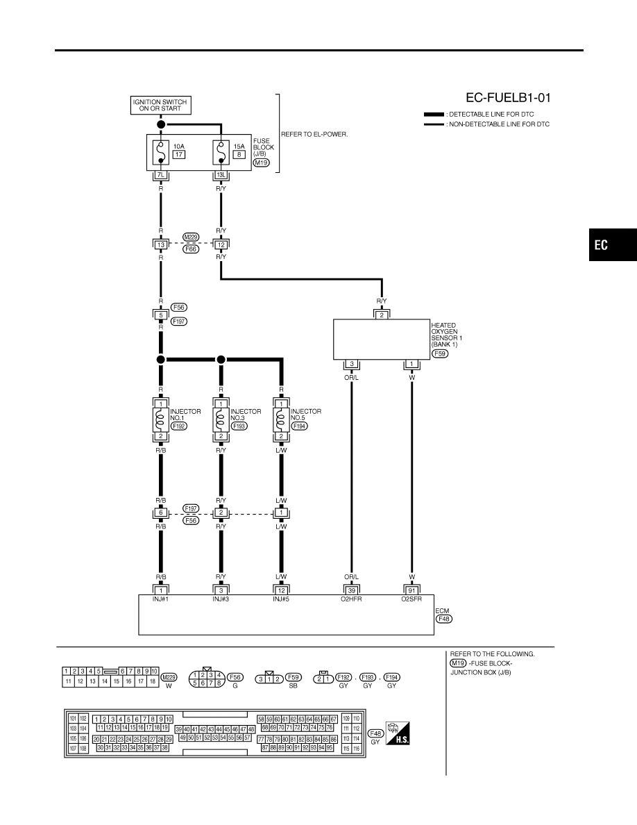
Wiring Diagram
NHEC0914
BANK 1
NHEC0914S01
MEC545D
GI
MA
EM
LC
FE
AT
AX
SU
BR
ST
RS
BT
HA
SC
EL
IDX
DTC P0171, P0174 FUEL INJECTION SYSTEM FUNCTION
Wiring Diagram
EC-275
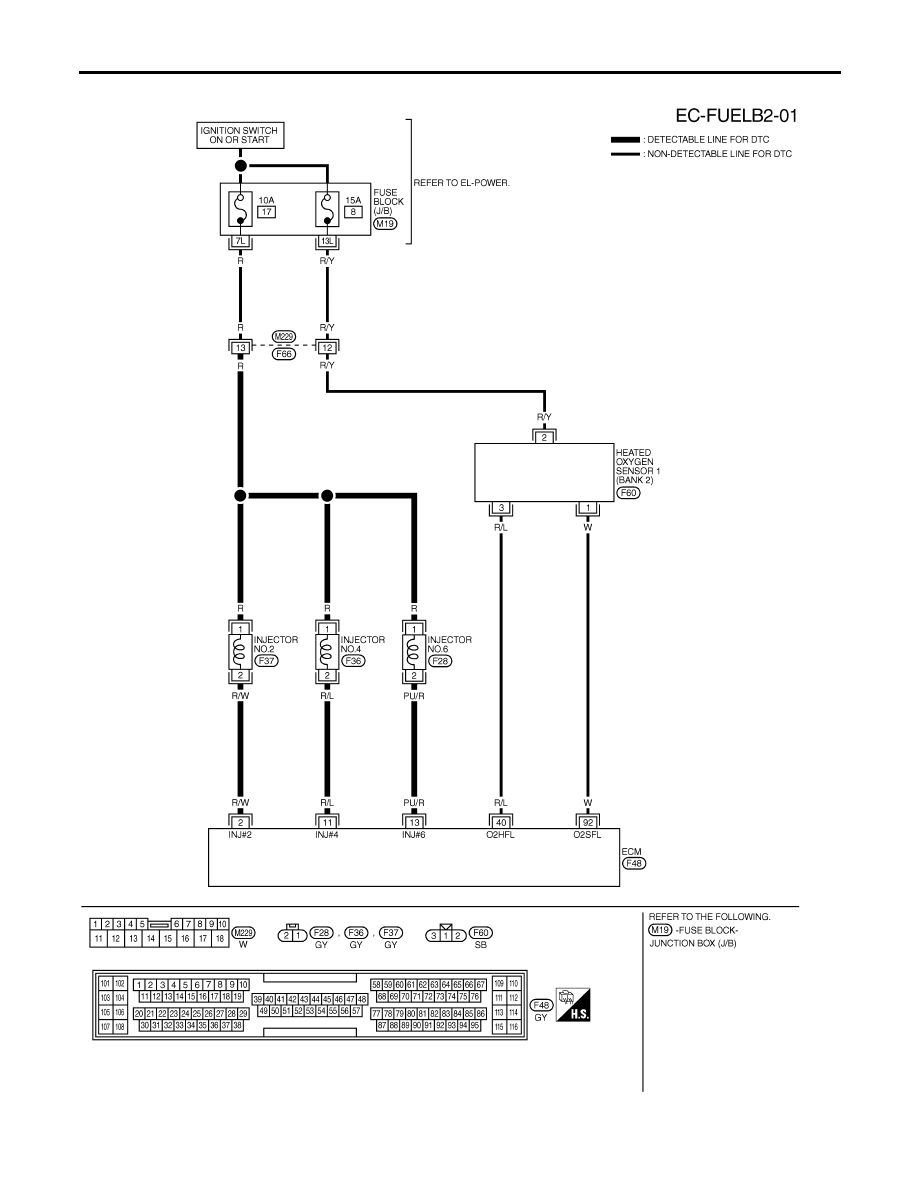
BANK 2
NHEC0914S02
MEC546D
DTC P0171, P0174 FUEL INJECTION SYSTEM FUNCTION
Wiring Diagram (Cont’d)
EC-276
Нет комментариевНе стесняйтесь поделиться с нами вашим ценным мнением.
Текст