Infiniti I35 (A33). Manual — part 234
Diagnostic Procedure
NHEC0915
1
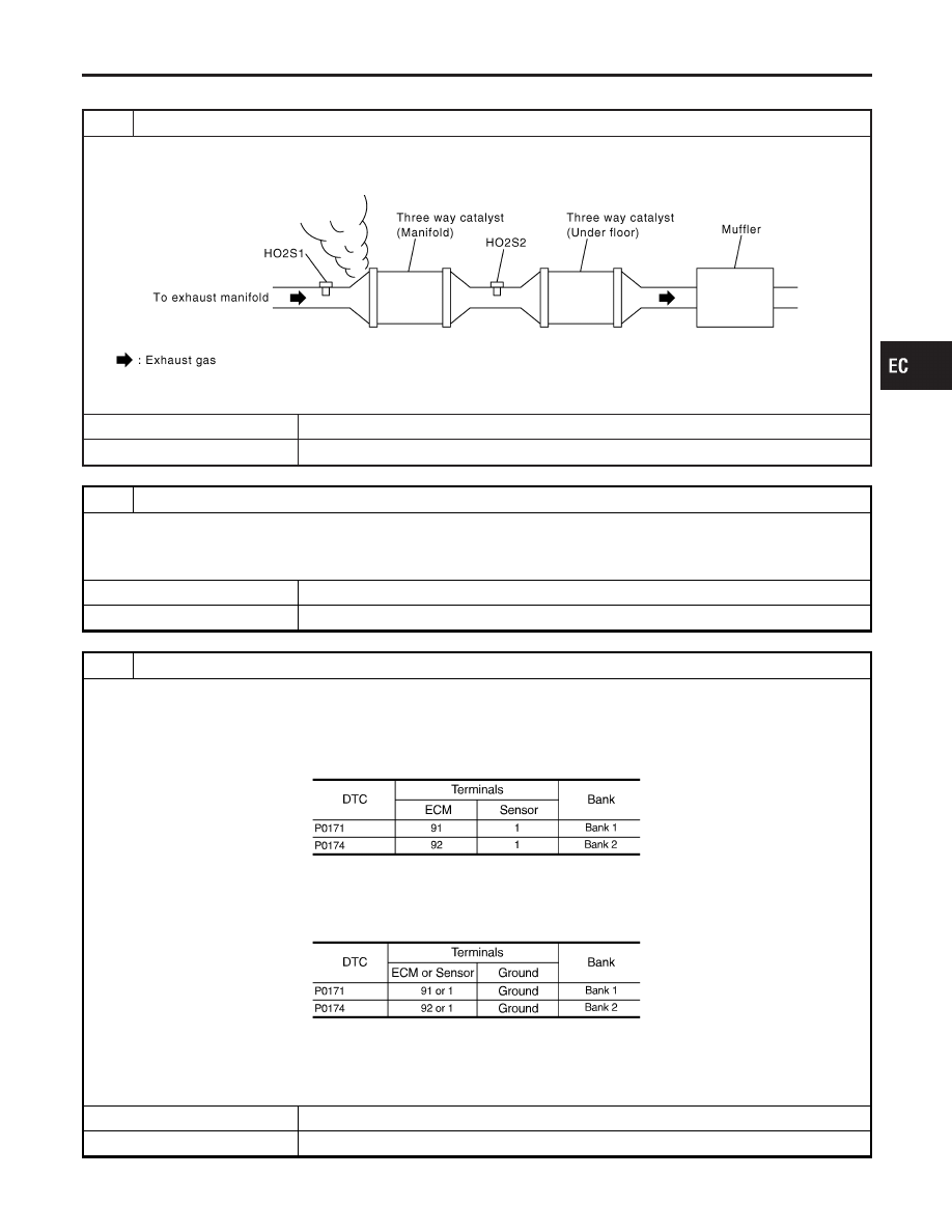
CHECK EXHAUST GAS LEAK
1. Start engine and run it at idle.
2. Listen for an exhaust gas leak before three way catalyst (manifold).
SEC502D
OK or NG
OK
©
GO TO 2.
NG
©
Repair or replace.
2
CHECK FOR INTAKE AIR LEAK
1. Listen for an intake air leak after the mass air flow sensor.
2. Check PCV hose connection.
OK or NG
OK
©
GO TO 3.
NG
©
Repair or replace.
3
CHECK HEATED OXYGEN SENSOR 1 CIRCUIT FOR OPEN AND SHORT
1. Turn ignition switch OFF.
2. Disconnect corresponding heated oxygen sensor 1 harness connector.
3. Disconnect ECM harness connector.
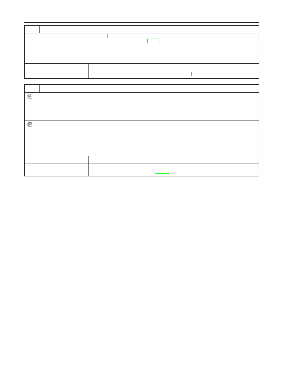
4. Check harness continuity between ECM terminal and HO2S1 terminal as follows.
Refer to Wiring Diagram.
MTBL1154
Continuity should exist.
5. Check harness continuity between ECM terminal or HO2S1 terminal and ground as follows.
Refer to Wiring Diagram.
MTBL1155
Continuity should not exist.
6. Also check harness for short to power.
OK or NG
OK
©
GO TO 4.
NG
©
Repair open circuit or short to ground or short to power in harness or connectors.
GI
MA
EM
LC
FE
AT
AX
SU
BR
ST
RS
BT
HA
SC
EL
IDX
DTC P0171, P0174 FUEL INJECTION SYSTEM FUNCTION
Diagnostic Procedure
EC-277
4
CHECK FUEL PRESSURE
1. Release fuel pressure to zero. Refer to EC-55.
2. Install fuel pressure gauge and check fuel pressure. Refer to EC-55.
At idling:
Approximately 350 kPa (3.57 kg/cm
2
, 51 psi)
OK or NG
OK
©
GO TO 5.
NG
©
Follow the instruction of “Fuel Pressure Check”, EC-55.
5
CHECK MASS AIR FLOW SENSOR
With CONSULT-II
1. Install all removed parts.
2. Check “MASS AIR FLOW” in “DATA MONITOR” mode with CONSULT-II.
2.0 - 6.0 g·m/sec: at idling
7.0 - 20.0 g·m/sec: at 2,500 rpm
With GST
1. Install all removed parts.
2. Check mass air flow sensor signal in MODE 1 with GST.
2.0 - 6.0 g·m/sec: at idling
7.0 - 20.0 g·m/sec: at 2,500 rpm
OK or NG
OK
©
GO TO 6.
NG
©
Check connectors for rusted terminals or loose connections in the mass air flow sensor
circuit or engine grounds. Refer to EC-197.
DTC P0171, P0174 FUEL INJECTION SYSTEM FUNCTION
Diagnostic Procedure (Cont’d)
EC-278
6
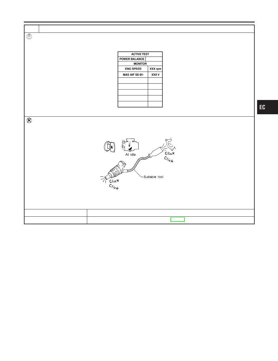
CHECK FUNCTION OF INJECTORS
With CONSULT-II
1. Start engine.
2. Perform “POWER BALANCE” in “ACTIVE TEST” mode with CONSULT-II.
SEC136D
3. Make sure that each circuit produces a momentary engine speed drop.
Without CONSULT-II
1. Start engine.
2. Listen to each injector operating sound.
MEC703B
Clicking noise should be heard.
OK or NG
OK
©
GO TO 7.
NG
©
Perform trouble diagnosis for “INJECTORS”, EC-696.
GI
MA
EM
LC
FE
AT
AX
SU
BR
ST
RS
BT
HA
SC
EL
IDX
DTC P0171, P0174 FUEL INJECTION SYSTEM FUNCTION
Diagnostic Procedure (Cont’d)
EC-279
7
CHECK INJECTOR
1. Confirm that the engine is cooled down and there are no fire hazards near the vehicle.
2. Turn ignition switch OFF.
3. Disconnect all injector harness connectors.
4. Remove injector gallery assembly. Refer to EC-56.
Keep fuel hose and all injectors connected to injector gallery.
5. For DTC P0171, reconnect injector harness connectors on bank 1.
For DTC P0174, reconnect injector harness connectors on bank 2.
6. Disconnect all ignition coil harness connectors.
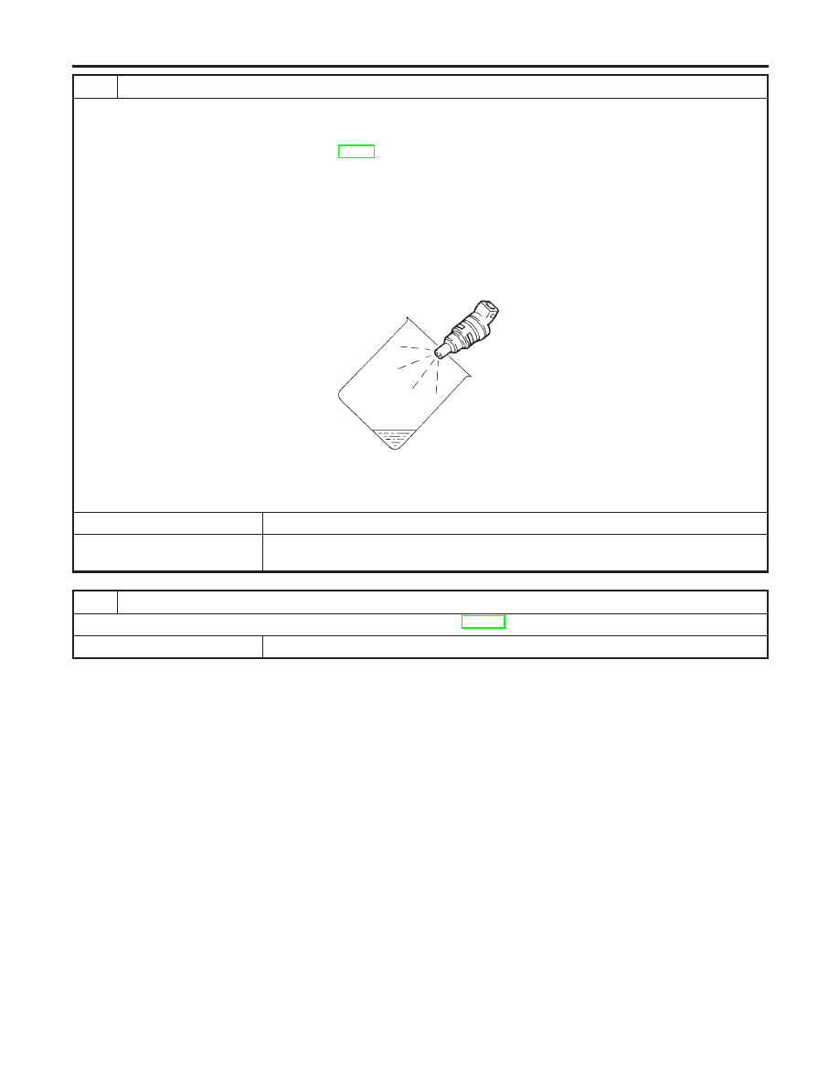
7. Prepare pans or saucers under each injector.
8. Crank engine for about 3 seconds.
For DTC P0171, make sure that fuel sprays out from injectors on bank 1.
For DTC P0174, make sure that fuel sprays out from injectors on bank 2.
SEF595Q
Fuel should be sprayed evenly for each injector.
OK or NG
OK
©
GO TO 8.
NG
©
Replace injectors from which fuel does not spray out. Always replace O-ring with new
ones.
8
CHECK INTERMITTENT INCIDENT
Refer to “TROUBLE DIAGNOSIS FOR INTERMITTENT INCIDENT”, EC-152.
©
INSPECTION END
DTC P0171, P0174 FUEL INJECTION SYSTEM FUNCTION
Diagnostic Procedure (Cont’d)
EC-280
Нет комментариевНе стесняйтесь поделиться с нами вашим ценным мнением.
Текст