Infiniti I35 (A33). Manual — part 12

Item
Display
Selection monitor item
Description
Remarks
TCM
INPUT
SIGNALS
MAIN
SIGNALS
SELEC-
TION
FROM
MENU
2 position switch
2 POSITION
SW
[ON/OFF]
X
—
H
I
ON/OFF status, com-
puted from signal of 2
position switch, is dis-
played.
1 position switch
1 POSITION
SW
[ON/OFF]
X
—
H
I
ON/OFF status, com-
puted from signal of 1
position switch, is dis-
played.
ASCD cruise signal
ASCD-CRUISE
[ON/OFF]
X
—
H
I
Status of ASCD
cruise signal is dis-
played.
ON ... Cruising state
OFF ... Normal run-
ning state
This is displayed even
when no ASCD is
mounted.
ASCD OD cut signal
ASCD-OD CUT
[ON/OFF]
X
—
H
I
Status of ASCD OD
release signal is dis-
played.
ON ... OD released
OFF ... OD not
released
This is displayed even
when no ASCD is
mounted.
Kickdown switch
KICKDOWN
SW
[ON/OFF]
X
—
H
I
ON/OFF status, com-
puted from signal of
kickdown switch, is
displayed.
This is displayed even
when no kickdown
switch is equipped.
A/T mode switch
POWER SHIFT
SW
[ON/OFF]
X
—
H
Not mounted but dis-
played.
Closed throttle position
signal
CLOSED
THL/SW
[ON/OFF]
X
—
H
I
ON/OFF status, com-
puted from signal of
closed throttle posi-
tion signal, is dis-
played.
This means closed
throttle position signal
input via CAN communi-
cation line.
Wide open throttle posi-
tion signal
W/O THRL/
P-SW
[ON/OFF]
X
—
H
I
ON/OFF status, com-
puted from signal of
wide open throttle
position signal, is dis-
played.
This means wide open
throttle position signal
input via CAN communi-
cation line.
Shift solenoid valve A
*SHIFT S/V A
[ON/OFF]
—
—
H
I
Displays status of
check signal (re-input
signal) for TCM con-
trol signal output.
Remains unchanged
when solenoid valves
are open or shorted.
Shift solenoid valve B
*SHIFT S/V B
[ON/OFF]
—
—
H
Overrun clutch solenoid
valve
*OVRRUN/C
S/V
[ON/OFF]
—
—
H
A/T mode switch
HOLD SW
[ON/OFF]
X
—
H
Not mounted but dis-
played.
GI
MA
EM
LC
EC
FE
AX
SU
BR
ST
RS
BT
HA
SC
EL
IDX
ON BOARD DIAGNOSTIC SYSTEM DESCRIPTION
CONSULT-II (Cont’d)
AT-45

Item
Display
Selection monitor item
Description
Remarks
TCM
INPUT
SIGNALS
MAIN
SIGNALS
SELEC-
TION
FROM
MENU
Stop lamp switch
BRAKE SW
[ON/OFF]
X
—
H
I
ON/OFF status is dis-
played.
ON ... Brake pedal is
depressed.
OFF ... Brake pedal is
released.
Gear position
GEAR
—
X
H
I
Gear position data
used for computation
by TCM, is displayed.
Selector lever position
SLCT LVR
POSI
—
X
H
I
Selector lever position
data, used for compu-
tation by TCM, is dis-
played.
A specific value used for
control is displayed if
fail-safe is activated due
to error.
Vehicle speed
VEHICLE
SPEED
[km/h] or [mph]
—
X
H
I
Vehicle speed data,
used for computation
by TCM, is displayed.
Throttle position
THROTTLE
POSI
[/8]
—
X
H
I
Throttle position data,
used for computation
by TCM, is displayed.
A specific value used for
control is displayed if
fail-safe is activated due
to error.
Line pressure duty
LINE PRES
DTY
[%]
—
X
H
I
Control value of line
pressure solenoid
valve, computed by
TCM from each input
signal, is displayed.
Torque converter clutch
solenoid valve duty
TCC S/V DUTY
[%]
—
X
H
I
Control value of
torque converter
clutch solenoid valve,
computed by TCM
from each input
signal, is displayed.
Shift solenoid valve A
SHIFT S/V A
[ON/OFF]
—
X
H
I
Control value of shift
solenoid valve A,
computed by TCM
from each input
signal, is displayed.
Control value of sole-
noid is displayed even if
solenoid circuit is dis-
connected.
The “OFF” signal is dis-
played if solenoid circuit
is shorted.
Shift solenoid valve B
SHIFT S/V B
[ON/OFF]
—
X
H
I
Control value of shift
solenoid valve B,
computed by TCM
from each input
signal, is displayed.
Overrun clutch solenoid
valve
OVERRUN/C
S/V
[ON/OFF]
—
X
H
I
Control value of over-
run clutch solenoid
valve computed by
TCM from each input
signal is displayed.
Self-diagnosis display
lamp
(A/T CHECK indicator
lamp)
SELF-D DP
LMP
[ON/OFF]
—
X
H
I
Control status of A/T
CHECK indicator
lamp is displayed.
ON BOARD DIAGNOSTIC SYSTEM DESCRIPTION
CONSULT-II (Cont’d)
AT-46
Item
Display
Selection monitor item
Description
Remarks
TCM
INPUT
SIGNALS
MAIN
SIGNALS
SELEC-
TION
FROM
MENU
Torque converter slip
ratio
TC SLIP RATIO
[0.000]
—
—
H
I
Ratio of engine revo-
lution to input shaft
revolution of torque
converter
Torque converter slip
speed
TC SLIP
SPEED
[rpm]
—
—
H
I
Difference in revolu-
tion between input
shaft revolution and
input shaft revolution
of torque converter
Display doesn’t indicate
0 rpm even if engine is
stopped.
But this isn’t malfunc-
tion.
Voltage
Voltage
[V]
—
—
H
I
Value measured by
voltage probe is dis-
played.
Frequency
Frequency
[Hz]
—
—
H
I
Value measured by
pulse probe is dis-
played. If measure-
ment is impossible,
“#” sign is displayed.
“#” sign is also dis-
played at the final
data value until the
measurement result is
obtained.
Duty cycle (high)
DUTY-HI
[%]
—
—
H
I
Duty cycle value for
measurement probe
is displayed.
Duty cycle (low)
DUTY-LOW
[%]
—
—
H
Plus width (high)
PLS WIDTH-HI
[msec]
—
—
H
I
Measured pulse width
of measurement
probe is displayed.
Plus width (low)
PLS WIDTH-
LOW
[msec]
—
—
H
X: Applicable
—: Not applicable
H
: Option
SAT585J
DTC WORK SUPPORT MODE WITH CONSULT-II
NHAT0022S04
CONSULT-II Setting Procedure
NHAT0022S0401
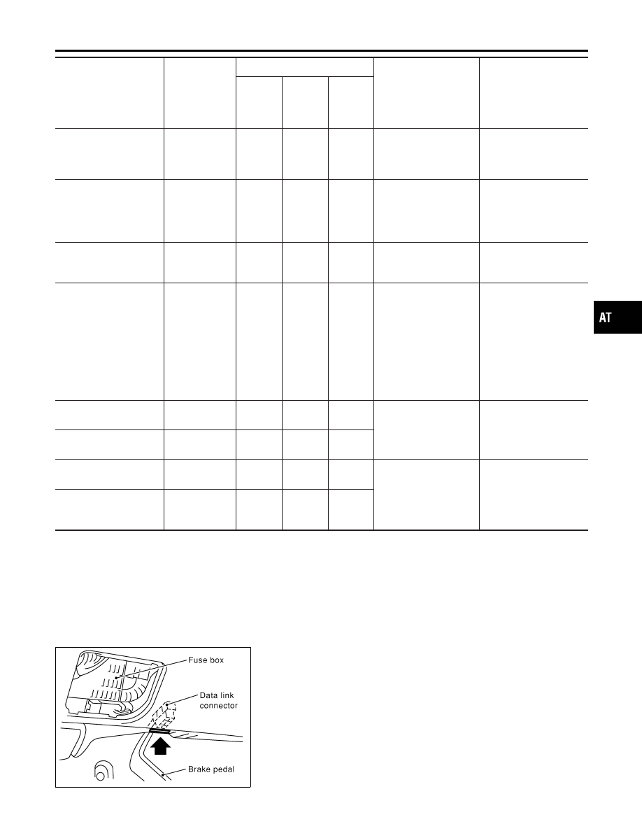
1.
Turn ignition switch OFF.
2.
Connect CONSULT-II and CONSULT-II CONVERTER to Data
link connector, which is located in left side dash panel.
GI
MA
EM
LC
EC
FE
AX
SU
BR
ST
RS
BT
HA
SC
EL
IDX
ON BOARD DIAGNOSTIC SYSTEM DESCRIPTION
CONSULT-II (Cont’d)
AT-47
SAT586J
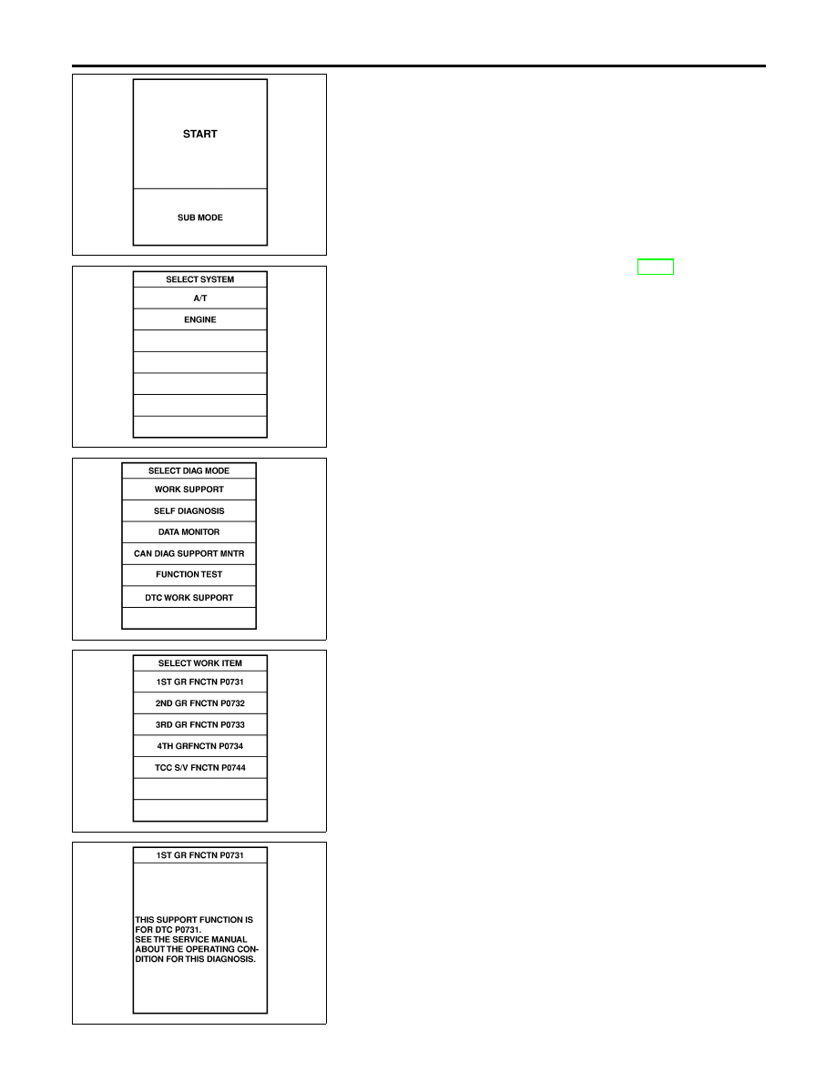
3.
Turn ignition switch ON.
4.
Touch “START”.
SAT014K
5.
Touch “A/T”. If “A/T” is not indicated, go to GI-42, “CONSULT-II
Data Link Connector (DLC) Circuit”.
SAT860K
6.
Touch “DTC WORK SUPPORT”.
SAT018K
7.
Touch select item menu (1ST, 2ND, etc.).
SAT589J
8.
Touch “START”.
ON BOARD DIAGNOSTIC SYSTEM DESCRIPTION
CONSULT-II (Cont’d)
AT-48
Нет комментариевНе стесняйтесь поделиться с нами вашим ценным мнением.
Текст