Infiniti I35 (A33). Manual — part 208
PBIB0193E
Component Inspection
NHEC1411
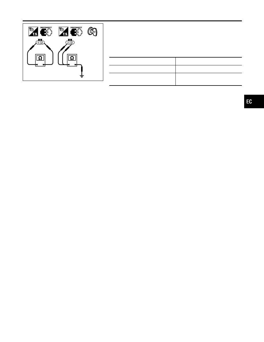
INTAKE VALVE TIMING CONTROL SOLENOID VALVE
1.
Disconnect intake valve timing control solenoid valve harness
connector.
2.
Check resistance between intake valve timing control solenoid
valve terminals as follows.
Terminals
Resistance
1 and 2
7.0 - 7.5
Ω
at 20°C (68°F)
1 or 2 and ground
∞Ω
(Continuity should not exist)
GI
MA
EM
LC
FE
AT
AX
SU
BR
ST
RS
BT
HA
SC
EL
IDX
DTC P0011, P0021 IVT CONTROL
Component Inspection
EC-173

Description
NHEC0826
SYSTEM DESCRIPTION
NHEC0826S01
Sensor
Input Signal to ECM
ECM func-
tion
Actuator
Crankshaft position sensor (POS)
Camshaft position sensor (PHASE)
Engine speed
Heated
oxygen
sensor 1
heater con-
trol
Heated oxygen sensor 1 heater
Engine coolant temperature sensor
Engine coolant temperature
The ECM performs ON/OFF control of the heated oxygen sensor 1 heaters corresponding to the engine speed
and engine coolant temperature. The duty percent varies with engine coolant temperature when engine is
started.
OPERATION
NHEC0826S02
Engine speed
rpm
Heated oxygen sensor 1 heater
Above 3,600
OFF
Below 3,600 after warming up
ON
CONSULT-II Reference Value in Data Monitor
Mode
NHEC0827
Specification data are reference values.
MONITOR ITEM
CONDITION
SPECIFICATION
HO2S1 HTR (B1)
HO2S1 HTR (B2)
I
Engine: After warming up
I
Engine speed: Below 3,600 rpm
ON
I
Engine speed: Above 3,600 rpm
OFF
On Board Diagnosis Logic
NHEC0829
DTC No.
Trouble diagnosis
name
DTC Detecting Condition
Possible Cause
P0031
0031
(Bank 1)
P0051
0051
(Bank 2)
Heated oxygen sen-
sor 1 heater control
circuit low
The current amperage in the heated oxygen sen-
sor 1 heater circuit is out of the normal range.
(An excessively low voltage signal is sent to ECM
through the heated oxygen sensor 1 heater.)
I
Harness or connectors
(The heated oxygen sensor 1 heater
circuit is open or shorted.)
I
Heated oxygen sensor 1 heater
P0032
0032
(Bank 1)
P0052
0052
(Bank 2)
Heated oxygen sen-
sor 1 heater control
circuit high
The current amperage in the heated oxygen sen-
sor 1 heater circuit is out of the normal range.
(An excessively high voltage signal is sent to ECM
through the heated oxygen sensor 1 heater.)
I
Harness or connectors
(The heated oxygen sensor 1 heater
circuit is shorted.)
I
Heated oxygen sensor 1 heater
DTC P0031, P0032, P0051, P0052 HO2S1 HEATER
Description
EC-174
SEF174Y
DTC Confirmation Procedure
NHEC0830
NOTE:
If DTC Confirmation Procedure has been previously conducted,
always turn ignition switch OFF and wait at least 10 seconds before
conducting the next test.
TESTING CONDITION:
Before performing the following procedure, confirm that bat-
tery voltage is between 10.5V and 16V at idle.
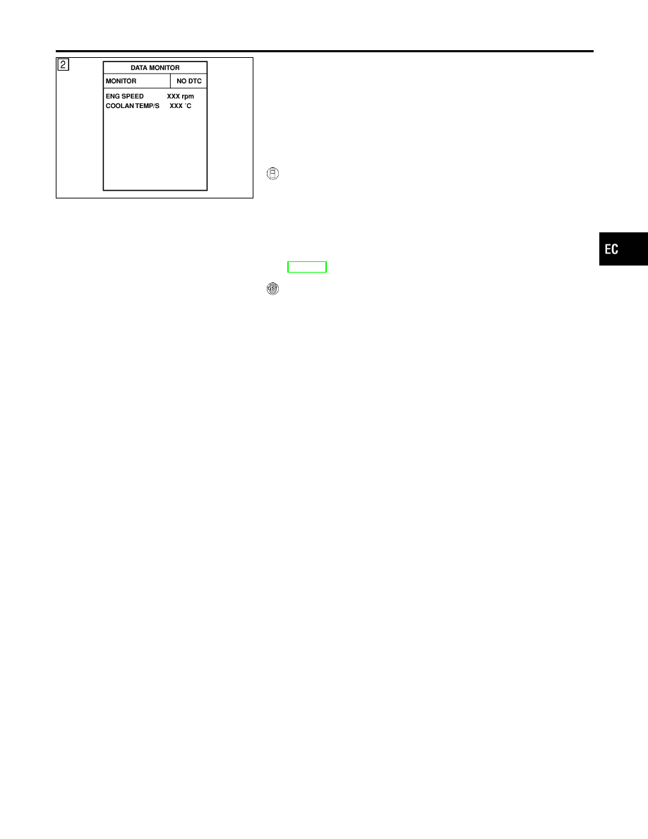
WITH CONSULT-II
NHEC0830S01
1)
Start engine and warm it up to normal operating temperature.
2)
Turn ignition switch OFF and wait at least 10 seconds.
3)
Turn ignition switch ON and select “DATA MONITOR” mode
with CONSULT-II.
4)
Start engine and run it for at least 6 seconds at idle speed.
5)
If 1st trip DTC is detected, go to “Diagnostic Procedure”,
EC-178.
WITH GST
NHEC0830S02
Follow the procedure “WITH CONSULT-II” above.
GI
MA
EM
LC
FE
AT
AX
SU
BR
ST
RS
BT
HA
SC
EL
IDX
DTC P0031, P0032, P0051, P0052 HO2S1 HEATER
DTC Confirmation Procedure
EC-175
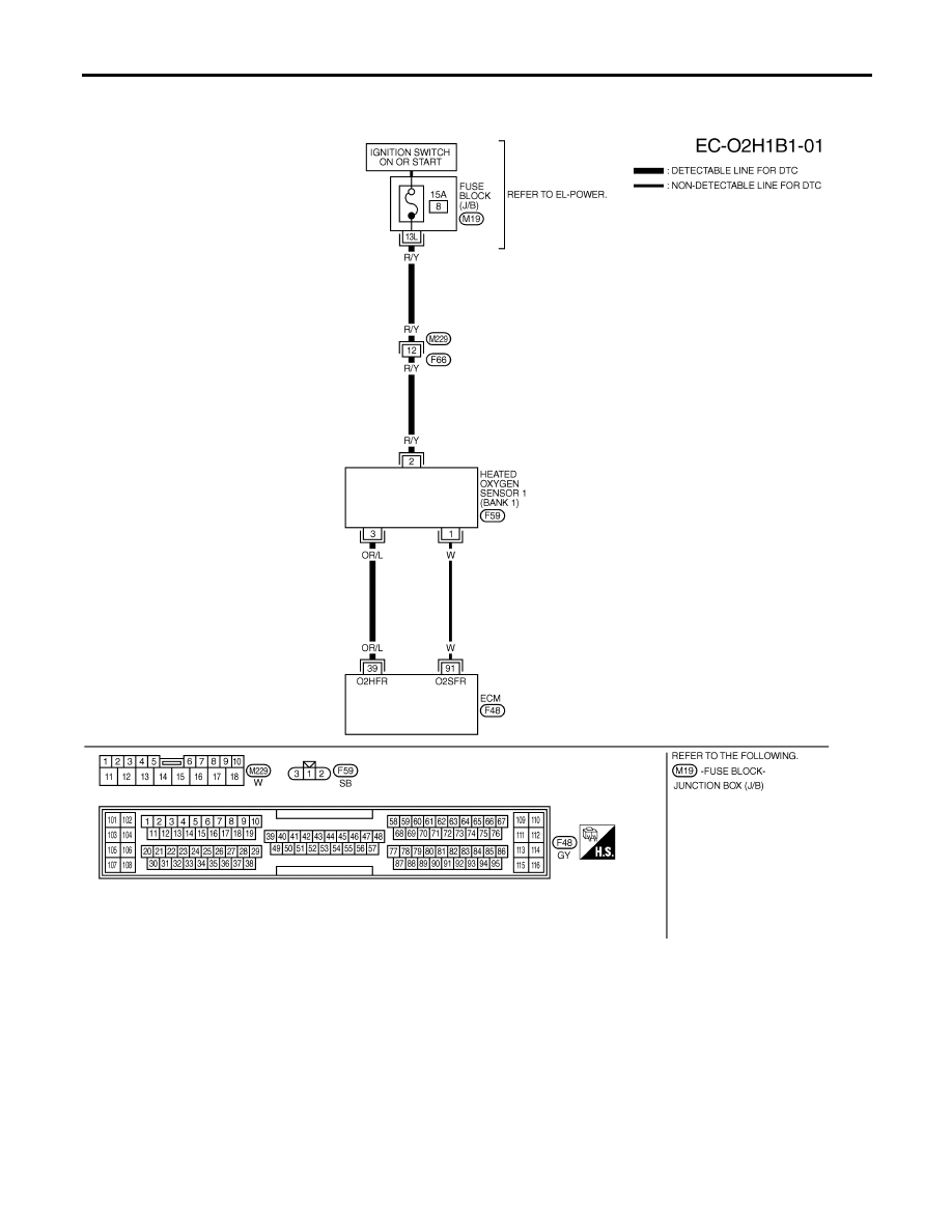
Wiring Diagram
NHEC0831
BANK 1
NHEC0831S01
MEC539D
DTC P0031, P0032, P0051, P0052 HO2S1 HEATER
Wiring Diagram
EC-176
Нет комментариевНе стесняйтесь поделиться с нами вашим ценным мнением.
Текст