Infiniti I35 (A33). Manual — part 341
4
CHECK STARTING SYSTEM
Turn ignition switch OFF, then turn it to START.
Does starter motor operate?
Yes or No
Yes
©
GO TO 5.
No
©
Refer to SC-10, “STARTING SYSTEM”.
5
CHECK FUSE
1. Turn ignition switch OFF.
2. Disconnect 10A fuse.
3. Check if 10A fuse is OK.
OK or NG
OK
©
GO TO 6.
NG
©
Replace 10A fuse.
6
CHECK START SIGNAL INPUT SIGNAL CIRCUIT FOR OPEN AND SHORT
1. Disconnect ECM harness connector.
2. Disconnect ignition switch harness connector.
3. Check harness continuity between ECM terminal 42 and ignition switch terminal 6. Refer to Wiring Diagram.
Continuity should exist.
4. Also check harness for short to ground and short to power.
OK or NG
OK
©
GO TO 8.
NG
©
GO TO 7.
7
DETECT MALFUNCTIONING PART
Check the following.
I
Harness connectors F66, M229
I
Fuse block (J/B) connectors M17, E83
I
Harness for open or short between ignition switch and ECM
©
Repair open circuit or short to ground or short to power in harness or connectors.
8
CHECK INTERMITTENT INCIDENT
Refer to “TROUBLE DIAGNOSIS FOR INTERMITTENT INCIDENT”, EC-152.
©
INSPECTION END
GI
MA
EM
LC
FE
AT
AX
SU
BR
ST
RS
BT
HA
SC
EL
IDX
START SIGNAL
Diagnostic Procedure (Cont’d)
EC-705
System Description
NHEC0392
Sensor
Input Signal to ECM
ECM func-
tion
Actuator
Crankshaft position sensor (POS)
Camshaft position sensor (PHASE)
Engine speed
Fuel pump
control
Fuel pump relay
Ignition switch
Start signal
The ECM activates the fuel pump for several seconds after the ignition switch is turned on to improve engine
startability. If the ECM receives a 120° signal from the camshaft position sensor (PHASE), it knows that the
engine is rotating, and causes the pump to operate. If the 120° signal is not received when the ignition switch
is on, the engine stalls. The ECM stops pump operation and prevents battery discharging, thereby improving
safety. The ECM does not directly drive the fuel pump. It controls the ON/OFF fuel pump relay, which in turn
controls the fuel pump.
Condition
Fuel pump operation
Ignition switch is turned to ON.
Operates for 1 second.
Engine running and cranking
Operates.
When engine is stopped
Stops in 1.5 seconds.
Except as shown above
Stops.
SEC088D
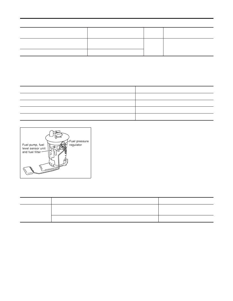
Component Description
NHEC0393
The fuel pump with a fuel damper is an in-tank type (the pump and
damper are located in the fuel tank).
CONSULT-II Reference Value in Data Monitor
Mode
NHEC0394
Specification data are reference values.
MONITOR ITEM
CONDITION
SPECIFICATION
FUEL PUMP RLY
I
Ignition switch is turned to ON. (Operates for 1 second.)
I
Engine running and cranking
ON
Except as shown above
OFF
FUEL PUMP
System Description
EC-706
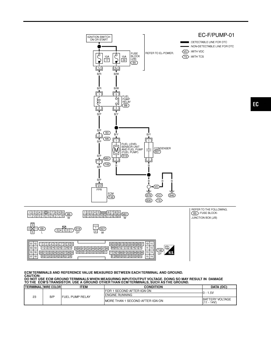
Wiring Diagram
NHEC0396
MEC648E
SEF639XC
GI
MA
EM
LC
FE
AT
AX
SU
BR
ST
RS
BT
HA
SC
EL
IDX
FUEL PUMP
Wiring Diagram
EC-707
Diagnostic Procedure
NHEC0397
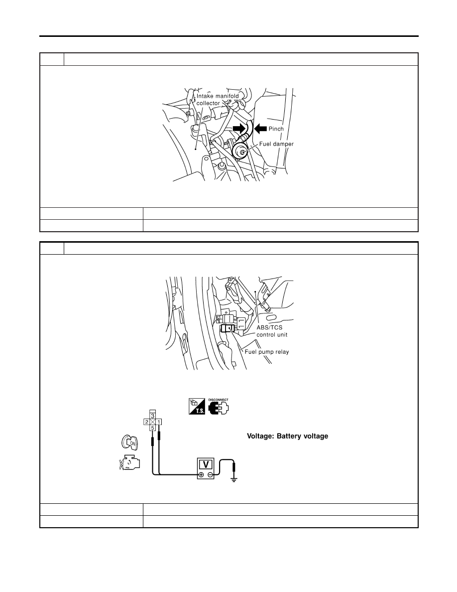
1
CHECK OVERALL FUNCTION
1. Turn ignition switch ON.
2. Pinch fuel feed hose with two fingers.
SEC089D
Fuel pressure pulsation should be felt on the fuel feed hose for 1 second after ignition switch is turned ON.
OK or NG
OK
©
INSPECTION END
NG
©
GO TO 2.
2
CHECK FUEL PUMP RELAY POWER SUPPLY CIRCUIT
1. Turn ignition switch OFF.
2. Disconnect fuel pump relay.
SEF284X
3. Turn ignition switch ON.
4. Check voltage between fuel pump relay terminals 1, 5 and ground with CONSULT-II or tester.
SEF898X
OK or NG
OK
©
GO TO 4.
NG
©
GO TO 3.
FUEL PUMP
Diagnostic Procedure
EC-708
Нет комментариевНе стесняйтесь поделиться с нами вашим ценным мнением.
Текст