Infiniti I35 (A33). Manual — part 342
3
DETECT MALFUNCTIONING PART
Check the following.
I
Fuse block (J/B) connector B5
I
10A fuse
I
15A fuse
I
Harness for open or short between fuse and fuel pump relay
©
Repair harness or connectors.
4
CHECK CONDENSER CIRCUIT FOR OPEN AND SHORT
1. Turn ignition switch OFF.
2. Disconnect condenser harness connector.
3. Check harness continuity between fuel pump relay terminal 3 and condenser terminal 1, condenser terminal 2 and
ground.
Refer to Wiring Diagram.
Continuity should exist.
4. Also check harness for short to ground and short to power.
OK or NG
OK
©
GO TO 6.
NG
©
GO TO 5.
5
DETECT MALFUNCTIONING PART
Check the following.
I
Harness for open or short between fuel pump relay and condenser
I
Harness for open or short between condenser and ground
©
Repair open circuit or short to ground or short to power in harness or connectors.
6
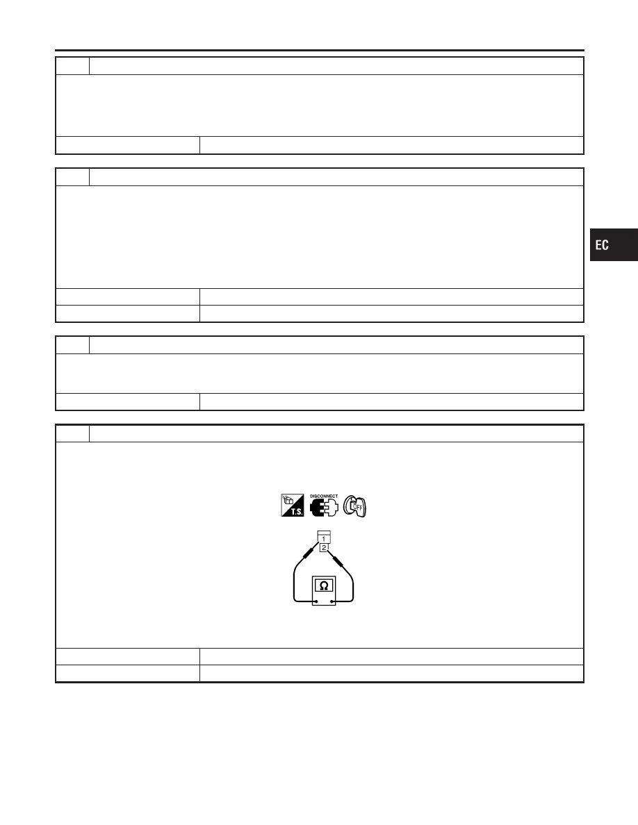
CHECK CONDENSER
1. Turn ignition switch OFF.
2. Disconnect condenser harness connector.
3. Check resistance between condenser terminals 1 and 2.
SEF124Y
Resistance: Above 1 M
Ω
at 25°C (77°F)
OK or NG
OK
©
GO TO 7.
NG
©
Replace condenser.
GI
MA
EM
LC
FE
AT
AX
SU
BR
ST
RS
BT
HA
SC
EL
IDX
FUEL PUMP
Diagnostic Procedure (Cont’d)
EC-709
7
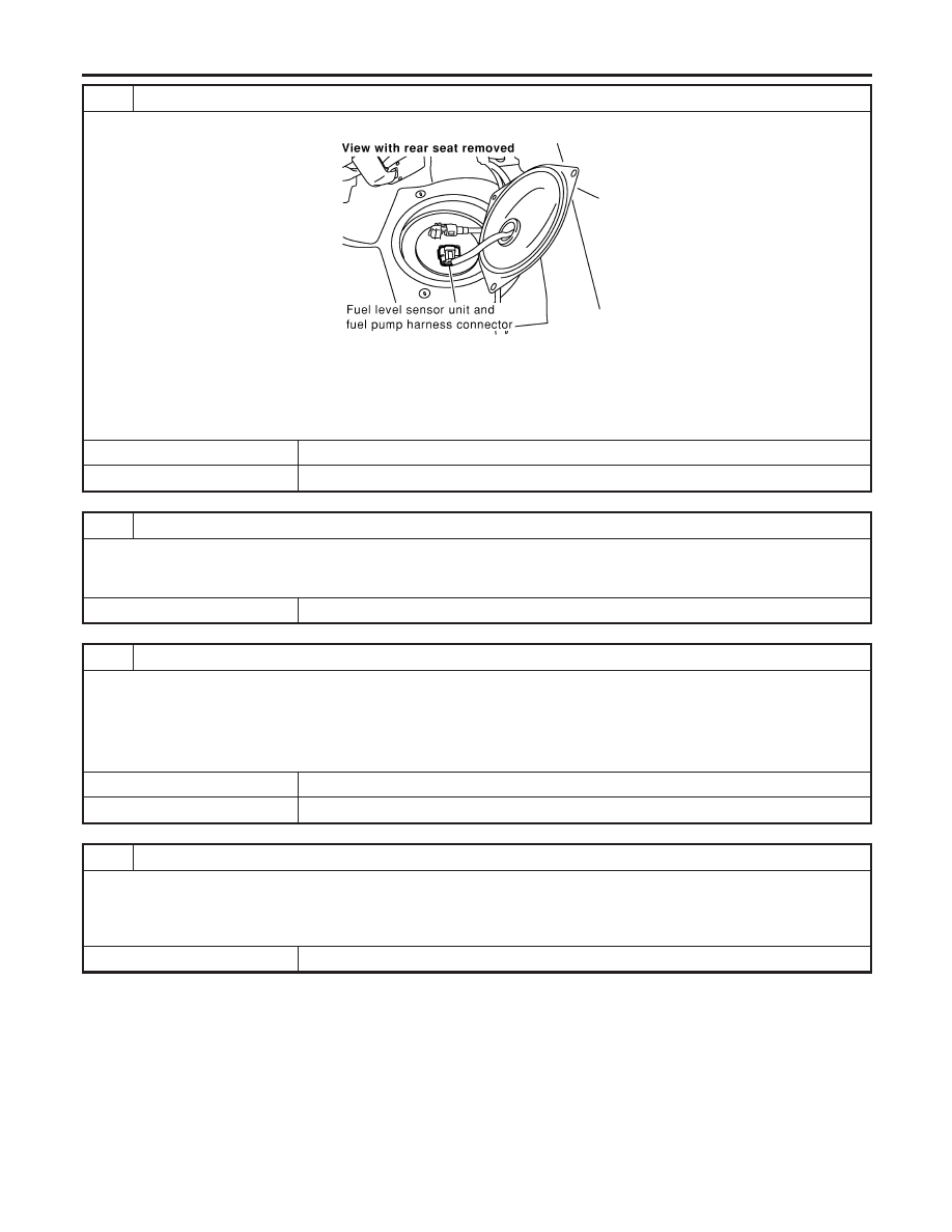
CHECK FUEL PUMP POWER SUPPLY AND GROUND CIRCUIT FOR OPEN AND SHORT
1. Disconnect “fuel level sensor unit and fuel pump” harness connector.
SEC082D
2. Check harness continuity between fuel pump terminal 3 and body ground, fuel pump terminal 1 and fuel pump relay
terminal 3. Refer to Wiring Diagram.
Continuity should exist.
3. Also check harness for short to ground and short to power.
OK or NG
OK
©
GO TO 9.
NG
©
GO TO 8.
8
DETECT MALFUNCTIONING PART
Check the following.
I
Harness for open or short between fuel pump relay and fuel pump
I
Harness for open or short between fuel pump and ground
©
Repair open circuit or short to ground or short to power in harness or connectors.
9
CHECK FUEL PUMP RELAY OUTPUT SIGNAL CIRCUIT FOR OPEN AND SHORT
1. Disconnect ECM harness connector.
2. Check harness continuity between ECM terminal 23 and fuel pump relay terminal 2. Refer to Wiring Diagram.
Continuity should exist.
3. Also check harness for short to ground and short to power.
OK or NG
OK
©
GO TO 11.
NG
©
GO TO 10.
10
DETECT MALFUNCTIONING PART
Check the following.
I
Harness connectors B3, M6
I
Harness connectors M81, F49
I
Harness for open or short between ECM and fuel pump relay
©
Repair open circuit or short to ground or short to power in harness or connectors.
FUEL PUMP
Diagnostic Procedure (Cont’d)
EC-710
11
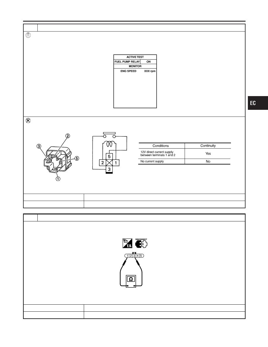
CHECK FUEL PUMP RELAY
With CONSULT-II
1. Reconnect fuel pump relay, “fuel level sensor unit and fuel pump” harness connector and ECM harness connector.
2. Turn ignition switch ON.
3. Turn fuel pump relay “ON” and “OFF” in “ACTIVE TEST” mode with CONSULT-II and check operating sound.
SEF073Y
Without CONSULT-II
Check continuity between terminals 3 and 5 under the following conditions.
SEF608X
OK or NG
OK
©
GO TO 12.
NG
©
Replace fuel pump relay.
12
CHECK FUEL PUMP
1. Disconnect fuel level sensor unit and fuel pump harness connector.
2. Check resistance between “fuel level sensor unit and fuel pump” terminals 1 and 3.
SEC918C
Resistance: 0.2 - 5.0
Ω
[at 25°C (77°F)]
OK or NG
OK
©
GO TO 13.
NG
©
Replace fuel pump.
GI
MA
EM
LC
FE
AT
AX
SU
BR
ST
RS
BT
HA
SC
EL
IDX
FUEL PUMP
Diagnostic Procedure (Cont’d)
EC-711

13
CHECK INTERMITTENT INCIDENT
Refer to “TROUBLE DIAGNOSIS FOR INTERMITTENT INCIDENT”, EC-152.
©
INSPECTION END
FUEL PUMP
Diagnostic Procedure (Cont’d)
EC-712
Нет комментариевНе стесняйтесь поделиться с нами вашим ценным мнением.
Текст