Infiniti I35 (A33). Manual — part 219
5
CHECK THROTTLE POSITION SENSOR 2 INPUT SIGNAL CIRCUIT FOR OPEN AND SHORT
1. Check harness continuity between ECM terminal 84 and electric throttle control actuator terminal 2.
Refer to Wiring Diagram.
Continuity should exist.
2. Also check harness for short to ground and short to power.
OK or NG
OK
©
GO TO 6.
NG
©
Repair open circuit or short to ground or short to power in harness or connectors.
6
CHECK THROTTLE POSITION SENSOR
Refer to “Component Inspection”, EC-217.
OK or NG
OK
©
GO TO 8.
NG
©
GO TO 7.
7
REPLACE ELECTRIC THROTTLE CONTROL ACTUATOR
1. Replace the electric throttle control actuator.
2. Perform “Throttle Valve Closed Position Learning”, EC-70.
3. Perform “Idle Air Volume Learning”, EC-70.
©
INSPECTION END
8
CHECK INTERMITTENT INCIDENT
Refer to “TROUBLE DIAGNOSIS FOR INTERMITTENT INCIDENT”, EC-152.
©
INSPECTION END
PBIB0968E
Component Inspection
NHEC1339
THROTTLE POSITION SENSOR
1.
Reconnect all harness connectors disconnected.
2.
Perform “Throttle Valve Closed Position Learning”, EC-70.
3.
Turn ignition switch ON.
4.
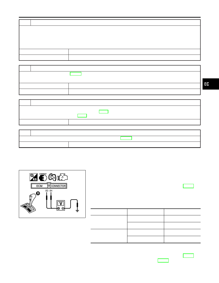
Set selector lever to D position.
5.
Check voltage between ECM terminals 83 (TP sensor 1), 84
(TP sensor 2) and ground under the following conditions.
Terminal
Accelerator pedal
Voltage
83
(Throttle position sensor
1)
Fully released
More than 0.36V
Fully depressed
Less than 4.75V
84
(Throttle position sensor
2)
Fully released
Less than 4.75V
Fully depressed
More than 0.36V
6.
If NG, replace electric throttle control actuator and go to the
next step.
7.
Perform “Throttle Valve Closed Position Learning”, EC-70.
8.
Perform “Idle Air Volume Learning”, EC-70.
GI
MA
EM
LC
FE
AT
AX
SU
BR
ST
RS
BT
HA
SC
EL
IDX
DTC P0122, P0123 TP SENSOR
Diagnostic Procedure (Cont’d)
EC-217
Description
NHEC0869
NOTE:
If DTC P0125 is displayed with P0117, P0118, first perform the
trouble diagnosis for DTC P0117, P0118. Refer to EC-206.
SEF594K
COMPONENT DESCRIPTION
NHEC0869S01
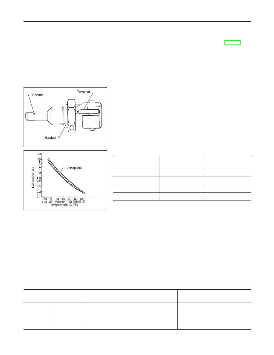
The engine coolant temperature sensor is used to detect the
engine coolant temperature. The sensor modifies a voltage signal
from the ECM. The modified signal returns to the ECM as the
engine coolant temperature input. The sensor uses a thermistor
which is sensitive to the change in temperature. The electrical
resistance of the thermistor decreases as temperature increases.
SEF012P
<Reference data>
Engine coolant
temperature
°C (°F)
Voltage*
V
Resistance
k
Ω
−10 (14)
4.4
7.0 - 11.4
20 (68)
3.5
2.1 - 2.9
50 (122)
2.2
0.68 - 1.00
90 (194)
0.9
0.236 - 0.260
*: This data is reference value and is measured between ECM terminal 93 (Engine
coolant temperature sensor) and ground.
CAUTION:
Do not use ECM ground terminals when measuring input/
output voltage. Doing so may result in damage to the ECM’s
transistor. Use a ground other than ECM terminals, such as
the ground.
On Board Diagnosis Logic
NHEC0870
This self-diagnosis has the one trip detection logic.
DTC No.
Trouble diagnosis
name
DTC Detecting Condition
Possible Cause
P0125
0125
Insufficient engine
coolant temperature
for closed loop fuel
control
I
Voltage sent to ECM from the sensor is not
practical, even when some time has passed
after starting the engine.
I
Engine coolant temperature is insufficient for
closed loop fuel control.
I
Harness or connectors
(High resistance in the circuit)
I
Engine coolant temperature sensor
I
Thermostat
DTC P0125 ECT SENSOR
Description
EC-218
SEF174Y
DTC Confirmation Procedure
NHEC0871
CAUTION:
Be careful not to overheat engine.
NOTE:
If DTC Confirmation Procedure has been previously conducted,
always turn ignition switch OFF and wait at least 10 seconds before
conducting the next test.
WITH CONSULT-II
NHEC0871S01
1)
Turn ignition switch ON.
2)
Select “DATA MONITOR” mode with CONSULT-II.
3)
Check that “COOLAN TEMP/S” is above 10°C (50°F).
If it is above 10°C (50°F), the test result will be OK.
If it is below 10°C (50°F), go to following step.
4)
Start engine and run it for 65 minutes at idle speed.
If “COOLAN TEMP/S” increases to more than 10°C (50°F)
within 65 minutes, stop engine because the test result will
be OK.
5)
If DTC is detected, go to “Diagnostic Procedure”, EC-219.
WITH GST
NHEC0871S02
Follow the procedure “WITH CONSULT-II” above.
Diagnostic Procedure
NHEC0872
1
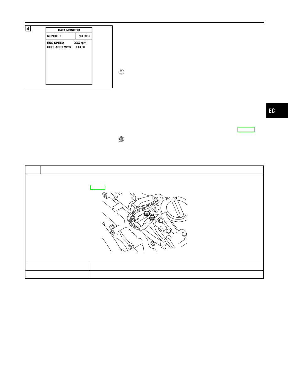
CHECK GROUND CONNECTIONS
1. Turn ignition switch OFF.
2. Loosen and retighten two engine ground screws.
Refer to “Ground Inspection”, EC-160.
SEC047D
OK or NG
OK
©
GO TO 2.
NG
©
Repair or replace ground connections.
GI
MA
EM
LC
FE
AT
AX
SU
BR
ST
RS
BT
HA
SC
EL
IDX
DTC P0125 ECT SENSOR
DTC Confirmation Procedure
EC-219
2
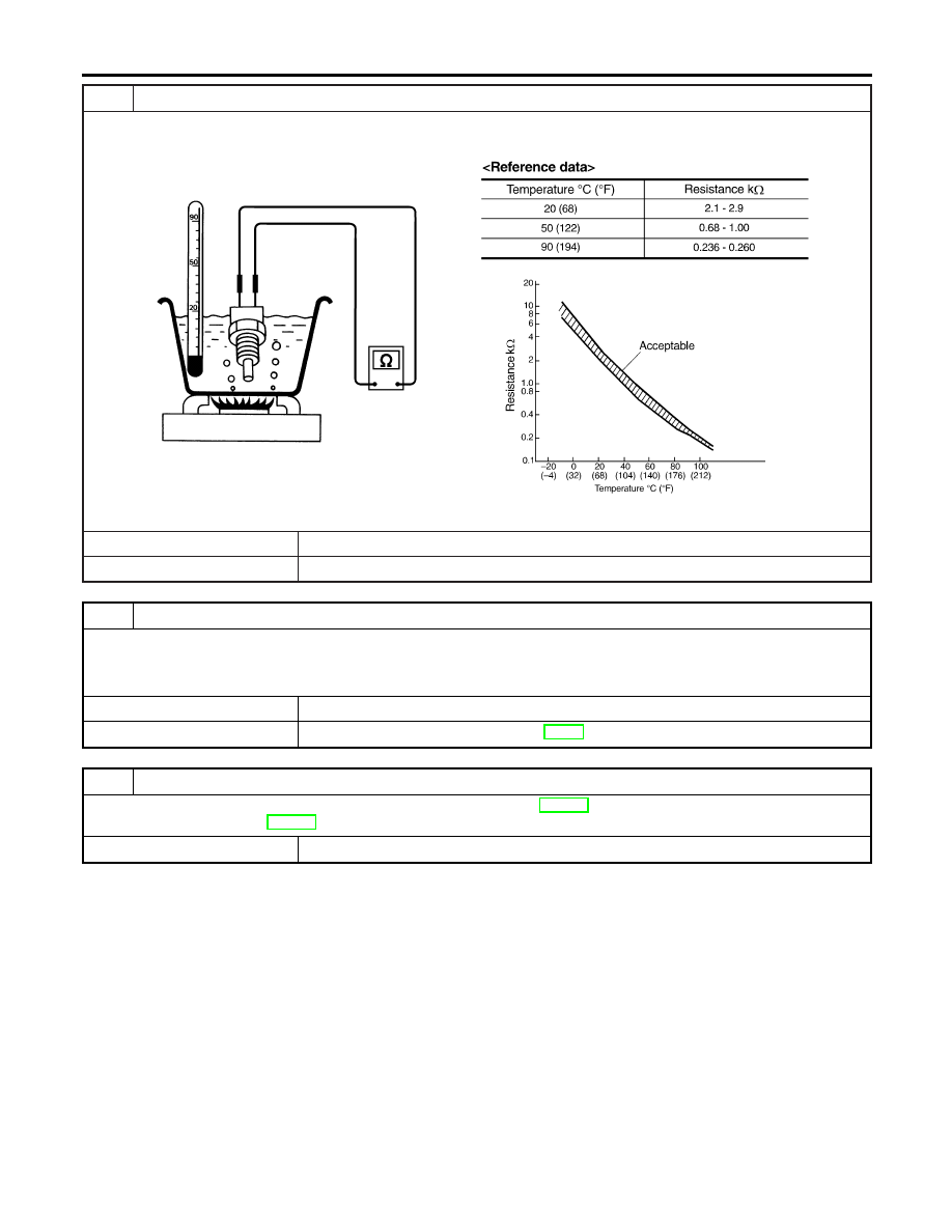
CHECK ENGINE COOLANT TEMPERATURE SENSOR
Check resistance between engine coolant temperature sensor terminals 1 and 2 as shown in the figure.
SEF304X
OK or NG
OK
©
GO TO 3.
NG
©
Replace engine coolant temperature sensor.
3
CHECK THERMOSTAT OPERATION
When the engine is cold [lower than 70°C (158°F)] condition, grasp lower radiator hose and confirm the engine coolant
does not flow.
OK or NG
OK
©
GO TO 4.
NG
©
Repair or replace thermostat. Refer to LC-18, “Thermostat”.
4
CHECK INTERMITTENT INCIDENT
I
Refer to “TROUBLE DIAGNOSIS FOR INTERMITTENT INCIDENT”, EC-152.
I
Refer to Wiring Diagram, EC-208.
©
INSPECTION END
DTC P0125 ECT SENSOR
Diagnostic Procedure (Cont’d)
EC-220
Нет комментариевНе стесняйтесь поделиться с нами вашим ценным мнением.
Текст