Infiniti I35 (A33). Manual — part 217
Diagnostic Procedure
NHEC0861
1
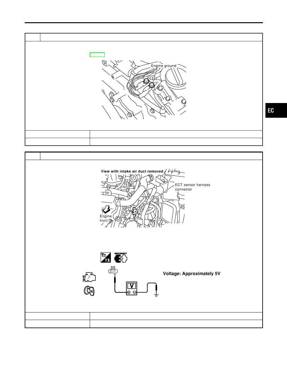
CHECK GROUND CONNECTIONS
1. Turn ignition switch OFF.
2. Loosen and retighten two engine ground screws.
Refer to “Ground Inspection”, EC-160.
SEC047D
OK or NG
OK
©
GO TO 2.
NG
©
Repair or replace ground connections.
2
CHECK ECT SENSOR POWER SUPPLY CIRCUIT
1. Disconnect engine coolant temperature (ECT) sensor harness connector.
SEC105D
2. Turn ignition switch ON.
3. Check voltage between ECT sensor harness connector terminal 1 and ground with CONSULT-II or tester.
SEC106D
OK or NG
OK
©
GO TO 4.
NG
©
GO TO 3.
GI
MA
EM
LC
FE
AT
AX
SU
BR
ST
RS
BT
HA
SC
EL
IDX
DTC P0117, P0118 ECT SENSOR
Diagnostic Procedure
EC-209
3
DETECT MALFUNCTIONING PART
Check harness for open or short between ECM and engine coolant temperature sensor.
©
Repair harness or connectors.
4
CHECK ECT SENSOR GROUND CIRCUIT FOR OPEN AND SHORT
1. Turn ignition switch OFF.
2. Disconnect ECM harness connector.
3. Disconnect TCM harness connector.
4. Check harness continuity between ECT sensor terminal 2 and ECM terminal 67, TCM terminal 42.
Refer to Wiring Diagram.
Continuity should exist.
5. Also check harness for short to power.
OK or NG
OK
©
GO TO 6.
NG
©
GO TO 5.
5
DETECT MALFUNCTIONING PART
Check the following.
I
Joint connector-20
I
Harness for open between ECM and engine coolant temperature sensor
I
Harness for open between TCM (Transmission Control Module) and engine coolant temperature sensor
©
Repair open circuit or short to power in harness or connectors.
6
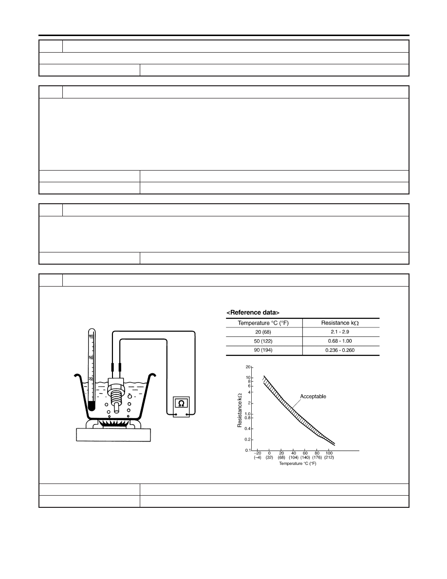
CHECK ENGINE COOLANT TEMPERATURE SENSOR
Check resistance between engine coolant temperature sensor terminals 1 and 2 as shown in the figure.
SEF304X
OK or NG
OK
©
GO TO 7.
NG
©
Replace engine coolant temperature sensor.
DTC P0117, P0118 ECT SENSOR
Diagnostic Procedure (Cont’d)
EC-210

7
CHECK INTERMITTENT INCIDENT
Refer to “TROUBLE DIAGNOSIS FOR INTERMITTENT INCIDENT”, EC-152.
©
INSPECTION END
GI
MA
EM
LC
FE
AT
AX
SU
BR
ST
RS
BT
HA
SC
EL
IDX
DTC P0117, P0118 ECT SENSOR
Diagnostic Procedure (Cont’d)
EC-211

PBIB0145E
Component Description
NHEC1333
Electric throttle control actuator consists of throttle control motor,
throttle position sensor, etc. The throttle position sensor responds
to the throttle valve movement.
The throttle position sensor has the two sensors. These sensors
are a kind of potentiometers which transform the throttle valve
position into output voltage, and emit the voltage signal to the ECM.
In addition, these sensors detect the opening and closing speed of
the throttle valve and feed the voltage signals to the ECM. The
ECM judges the current opening angle of the throttle valve from
these signals and the ECM controls the throttle control motor to
make the throttle valve opening angle properly in response to driv-
ing condition.
CONSULT-II Reference Value in Data Monitor
Mode
NHEC1334
Specification data are reference values.
MONITOR ITEM
CONDITION
SPECIFICATION
THRTL SEN2*
I
Ignition switch:
ON (Engine stopped)
I
Shift lever: D
Accelerator pedal: Released
More than 0.36V
Accelerator pedal: Fully depressed
Less than 4.75V
*: Throttle position sensor 2 signal is converted by ECM internally. Thus, it differs from ECM terminal voltage signal.
On Board Diagnosis Logic
NHEC1455
These self-diagnoses have the one trip detection logic.
NOTE:
If DTC P0122 or P0123 is displayed with DTC P1229, first perform the trouble diagnosis for DTC P1229.
Refer to EC-539.
DTC No.
Trouble diagnosis
name
DTC Detecting Condition
Possible Cause
P0122
0122
Throttle position sen-
sor 2 circuit low input
An excessively low voltage from the TP sensor 2
is sent to ECM.
I
Harness or connectors
(The TP sensor 2 circuit is open or
shorted.)
I
Electric throttle control actuator (TP
sensor 2)
P0123
0123
Throttle position sen-
sor 2 circuit high
input
An excessively high voltage from the TP sensor 2
is sent to ECM.
FAIL-SAFE MODE
NHEC1455S01
When the malfunction is detected, ECM enters fail-safe mode and the MIL lights up.
Engine operation condition in fail-safe mode
The ECM controls the electric throttle control actuator in regulating the throttle opening in order for the idle position to be within
+10 degrees.
The ECM regulates the opening speed of the throttle valve to be slower than the normal condition.
So, the acceleration will be poor.
DTC P0122, P0123 TP SENSOR
Component Description
EC-212
Нет комментариевНе стесняйтесь поделиться с нами вашим ценным мнением.
Текст