Infiniti I35 (A33). Manual — part 132
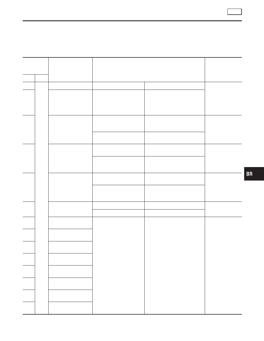
Control Unit Input/Output Signal Standard
NHBR0263
STANDARDS USING A CIRCUIT TESTER AND
OSCILLOSCOPE
NHBR0263S01
CAUTION:
Connect the connectors for the VDC/TCS/ABS control unit and
actuator, and turn the ignition switch ON.
Measure-
ment termi-
nal
Measuring point
Standard value (Note 1)
(Reference) Check
items for malfunc-
tion
+
−
1
Body
ground
Power supply
Ignition switch ON
Battery voltage (Approx. 12V)
Control unit power
supply circuit
2
Actuator motor relay,
actuator relay power
supply and steering
angle sensor power sup-
ply
Ignition switch ON
Battery voltage (Approx. 12V)
7
Actuator motor relay
Actuator motor being driven
(“Active test” mode with CON-
SULT-II)
Approx. 0V
Actuator motor,
motor relay, and
circuit
Actuator motor while the
vehicle is stopped
Battery voltage (Approx. 12V)
36
Actuator relay
When actuator relay is active.
(the engine running)
Approx. 0V
Actuator relay and
circuit
When actuator relay is inac-
tive.
(Fail-safe, engine starts.)
Battery voltage (Approx. 12V)
20
Actuator motor monitor
When actuator relay is active.
(the engine running)
Battery voltage (Approx. 12V)
Actuator motor
monitor circuit
When actuator relay is inac-
tive.
(Fail-safe, engine starts.)
Approx. 0V
42
PNP switch
Shift lever position: N
Battery voltage (Approx. 12V)
PNP switch and
circuit
Except N
Approx. 0V
3
Front LH outlet solenoid
valve
Solenoid valve activated
(In “active test” mode of
CONSULT-II) or actuator relay
inactive (in fail-safe mode)
When solenoid valve is inac-
tive and actuator relay active
(when ignition switch ON)
Approx. 0V
Battery voltage (Approx. 12V)
Solenoid valve and
circuit
4
Rear RH outlet solenoid
valve
5
Front LH inlet solenoid
valve
6
Rear RH inlet solenoid
valve
25
Rear LH outlet solenoid
valve
26
Front RH inlet solenoid
valve
53
Rear LH inlet solenoid
valve
55
Front RH outlet solenoid
valve
GI
MA
EM
LC
EC
FE
AT
AX
SU
ST
RS
BT
HA
SC
EL
IDX
TROUBLE DIAGNOSIS — INTRODUCTION
VDC
Control Unit Input/Output Signal Standard
BR-113
Measure-
ment termi-
nal
Measuring point
Standard value (Note 1)
(Reference) Check
items for malfunc-
tion
+
−
49
Body
ground
Primary-side VDC
switch-over solenoid
valve 1 (USV)
When switch-over solenoid
valve is active (in “active test”
mode of CONSULT-II)
Or, when actuator relay inac-
tive (when fail-safe)
When switch-over solenoid
valve is inactive and actuator
relay is active (when ignition
switch ON)
Approx. 0V
Battery voltage (Approx. 12V)
Switch-over sole-
noid valve and cir-
cuit
50
Secondary-side VDC
switch-over solenoid
valve 1 (USV)
52
Secondary-side VDC
switch-over solenoid
valve 2 (MAV)
54
Primary-side VDC
switch-over solenoid
valve 2 (MAV)
8
10
Front LH wheel sensor
Wheel rotated (Approx. 30
km/h (19 MPH) (Note 2)
Pulse generation:
Approx. 200 Hz
Wheel speed sen-
sor and circuit
11
12
Rear RH wheel sensor
13
14
Rear LH wheel sensor
15
16
Front RH wheel sensor
48
Body
ground
Stop lamp signal
Depress brake pedal.
Battery voltage (Approx. 12V)
Stop lamp switch
and circuit
Release the brake pedal.
Approx. 0V
44
VDC OFF switch
VDC OFF switch is pressed.
Approx. 10V
VDC OFF switch
and circuit
VDC OFF switch is released.
Approx. 12V
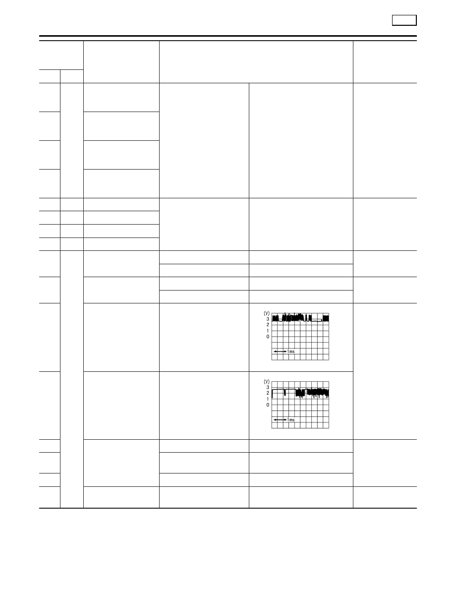
61
CAN communication
input/output signal (H)
Ignition switch ON
PBIA0224J
—
63
CAN communication
input/output signal (L)
Ignition switch ON
PBIA0223J
67
Pressure sensor
Ignition switch ON
Approx. 0V
Pressure sensor
and circuit
68
When ignition switch ON and
brake pedal released.
Approx. 0.6V
69
Ignition switch ON
Approx. 0V
18
Side G sensor
Ignition switch ON
Approx. 2.5V
Yaw rate /Side G
sensor and circuit
TROUBLE DIAGNOSIS — INTRODUCTION
VDC
Control Unit Input/Output Signal Standard (Cont’d)
BR-114
Measure-
ment termi-
nal
Measuring point
Standard value (Note 1)
(Reference) Check
items for malfunc-
tion
+
−
34
Body
ground
Yaw rate/Side G sensor
Ignition switch ON
Battery voltage (Approx. 12V)
Yaw rate /Side G
sensor and circuit
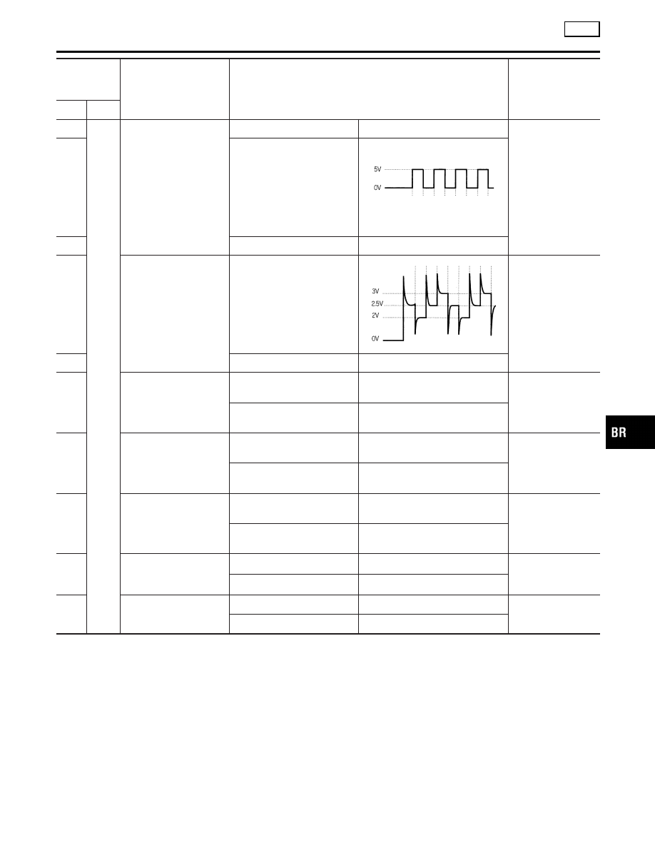
77
Ignition switch ON
SFIA0150E
78
Ignition switch ON
Approx. 2.5V
79
Yaw rate sensor
Ignition switch ON
SFIA0151E
Yaw rate sensor
and circuit
80
Ignition switch ON
Approx. 0V
30
ABS warning lamp
ABS warning lamp turns on
(Note 3)
Approx. 0V
ABS warning lamp
and circuit
ABS warning lamp turns off
(Note 3)
Battery voltage (Approx. 12V)
70
VDC OFF indicator lamp
VDC OFF indicator lamp
turns on (Note 4)
Approx. 0V
VDC OFF warning
lamp and circuit
VDC OFF indicator lamp
turns off (Note 4)
Battery voltage (Approx. 12V)
83
SLIP indicator lamp
When SLIP indicator lamp is
ON (Note 5)
Approx. 0V
SLIP indicator lamp
and circuit
SLIP indicator lamp turns off
(Note 5)
Battery voltage (Approx. 12V)
40
Brake fluid level warning
switch
Brake fluid is not enough
Approx. 0V
Brake fluid level
warning switch and
circuit
Brake fluid is enough
Battery voltage (Approx. 12V)
76
Parking brake signal
Apply the parking brake.
Approx. 0V
Parking brake
switch and circuit
Release the parking brake.
Battery voltage (Approx. 12V)
(Note 1): When the standard value is checked using a circuit tester for voltage measurement, the connector terminals should not extend
forcefully.
(Note 2): Check the pressure of the tire in normal condition.
(Note 3): ON/OFF timing of the ABS warning lamp
ON: When the ignition switch is turned ON (before engine start) or a malfunction is detected.
OFF: 2 seconds after the engine started (the system is in normal condition).
(Note 4): VDC OFF indicator lamp ON/OFF timing
ON: When the ignition switch is turned ON (before engine start) or a malfunction is detected, if the VDC OFF switch is ON.
OFF: 2 seconds after the engine started (the system is in normal condition) and VDC OFF switch is OFF.
(Note 5): ON/OFF timing of the SLIP indicator lamp
ON: When the ignition switch is turned ON (before engine start) or a malfunction is detected.
OFF: 2 seconds after the engine started (the system is in normal condition) and the VDC/TCS function is inactive.
Flashing: VDC/TCS function is active during driving.
GI
MA
EM
LC
EC
FE
AT
AX
SU
ST
RS
BT
HA
SC
EL
IDX
TROUBLE DIAGNOSIS — INTRODUCTION
VDC
Control Unit Input/Output Signal Standard (Cont’d)
BR-115

STANDARDS WITH CONSULT-II
NHBR0263S02
CAUTION:
The displayed item is the data calculated by the control unit,
so it may indicate a normal value even if an output circuit
(harness) is open or shorted.
Data monitor item
Contents
Data monitor
(Reference) Check items
for malfunction
Condition
Reference value
in normal opera-
tion
FR RH SENSOR
FR LH SENSOR
RR RH SENSOR
RR LH SENSOR
Wheel speed (Note 1)
Vehicle stopped
0 [km/h (MPH)]
Wheel speed sensor cir-
cuit
During driving
Almost in accor-
dance with the
speedometer dis-
play (within
±
10%)
ACCEL POS SIG
Open/close condition
of throttle valve (linked
with accelerator pedal)
Accelerator pedal not
depressed (ignition switch is
ON)
0%
Control unit communica-
tion circuit between the
VDC/TCS/ABS control unit
and ECM
Accelerator pedal depressed
(ignition switch is ON)
0 - 100%
ENG RPM
With the engine run-
ning
With the engine stopped
0 rpm
Engine speed signal cir-
cuit
Engine running
Almost in accor-
dance with
tachometer dis-
play
STR ANGLE SIG
Steering angle
detected by steering
angle sensor
Straight-ahead condition
Approx. 0 deg.
Steering angle sensor and
circuit
Steering
−720 to 720 deg.
YAW RATE SEN
Yaw rate detected by
yaw rate sensor
Vehicle stopped
Approx. 0 d/s
Yaw rate sensor and cir-
cuit
During driving
−70 to 70 d/s
SIDE G-SENSOR
Transverse accelera-
tion detected by side G
sensor
Vehicle stopped
Approx. 0 m/s
2
Side G sensor and circuit
During driving
−24.3 to 24.1
m/s
2
PRESS SENSOR
Brake fluid pressure
detected by pressure
sensor
With the ignition switch turned
ON and brake pedal released.
Approx. 0 bar
Pressure sensor and cir-
cuit
With the ignition switch turned
ON and brake pedal
depressed.
−40 to 300 bar
BATTERY VOLT
Battery voltage sup-
plied to the VDC/TCS/
ABS control unit
Ignition switch ON
10 - 16V
VDC/TCS/ABS control unit
power supply circuit and
ground circuit
MOTOR RELAY
Motor relay
ON/OFF condition
ABS not activated.
OFF
Motor relay and circuit
ABS activated.
ON
ACTUATOR RLY
Actuator relay
ON/OFF condition
Ignition ON and Vehicle
stopped.
OFF
Actuator relay and circuit
Engine running and Vehicle
stopped.
ON
STOP LAMP SW
Operating status of
brake pedal
Depress brake pedal.
ON
Stop lamp switch circuit
Release the brake pedal.
OFF
TROUBLE DIAGNOSIS — INTRODUCTION
VDC
Control Unit Input/Output Signal Standard (Cont’d)
BR-116
Нет комментариевНе стесняйтесь поделиться с нами вашим ценным мнением.
Текст